TFT array substrate
- Summary
- Abstract
- Description
- Claims
- Application Information
AI Technical Summary
Benefits of technology
Problems solved by technology
Method used
Image
Examples
first embodiment
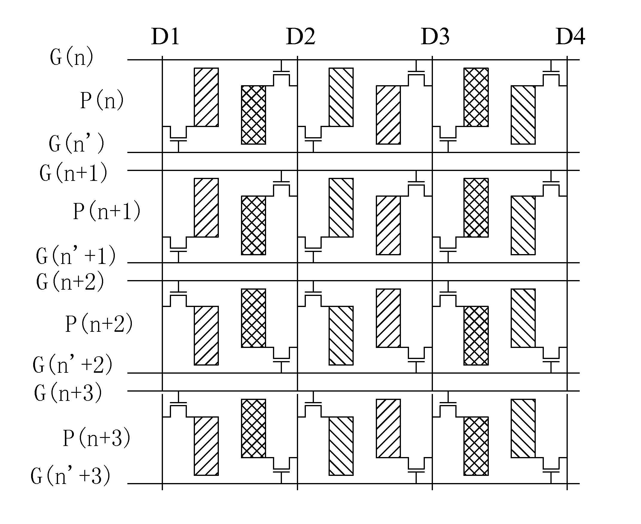
[0036]Referring to FIG. 5, a schematic view is given to illustrate a thin-film transistor (TFT array substrate) according to the present invention. The TFT array substrate comprises: a plurality of data lines, such as D1, D2, D3, D4, a plurality of scan lines, and a plurality of sub-pixels arranged in an array.
[0037]In each row of the sub-pixels, the sub-pixels of odd columns and the sub-pixels of even columns are staggered laterally on a plane.
[0038]Each of the data lines is electrically connected to two sub-pixels of each sub-pixel row that are located on left side and right side of the data line respectively by TFTs and supplies data signals to the two sub-pixels.
[0039]Two scan lines are provided, corresponding to and located at upper and lower sides of each sub-pixel row. The nth scan line G(n) and the (n′)th scan line G(n′) are respectively located on the upper and lower sides of the nth sub-pixel row P(n); the (n+1)th scan line G(n+1) and the (n′+1)th scan line G(n′+1) are res...
second embodiment
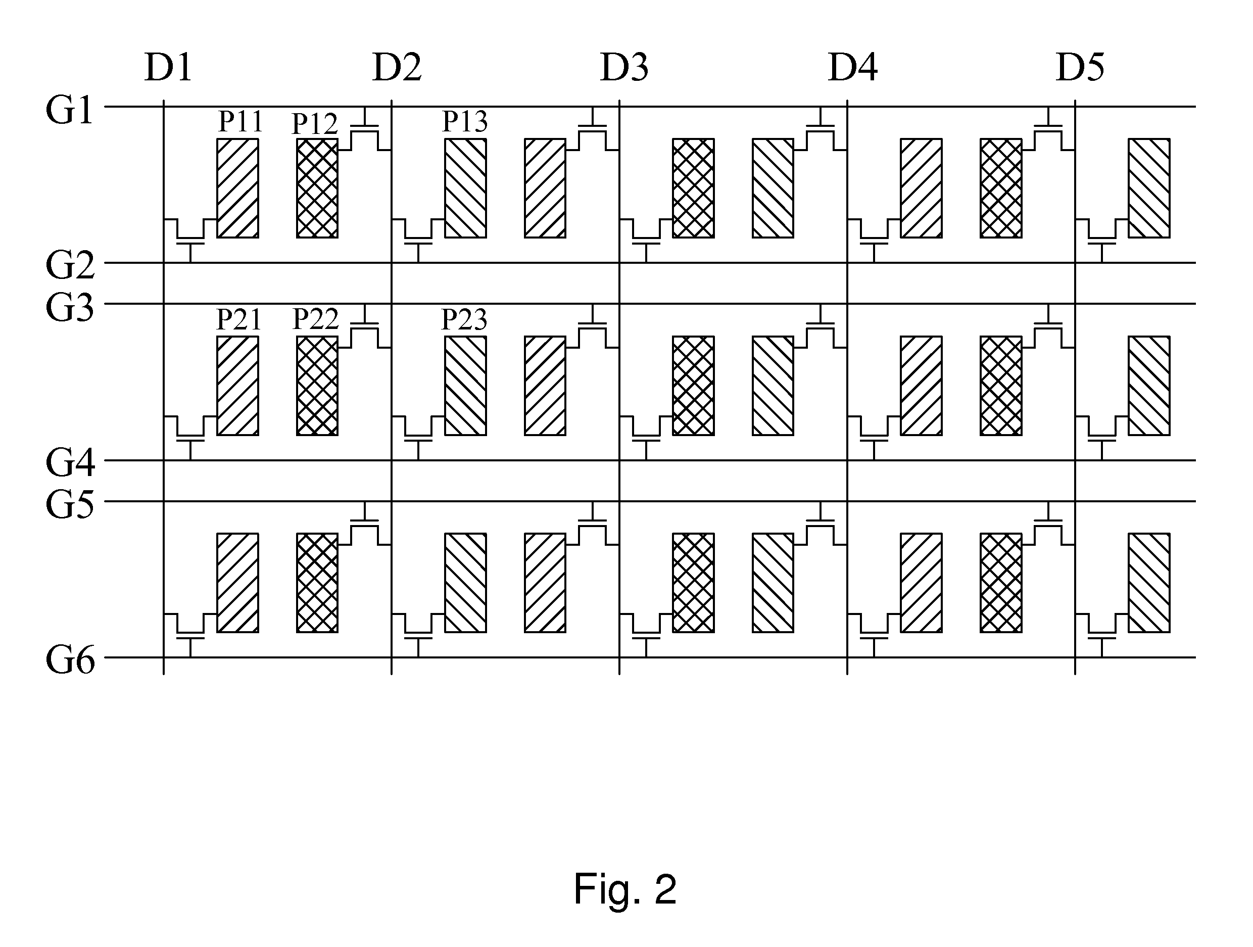
[0043]Referring to FIG. 6, a schematic view is given to illustrate a TFT array substrate according to the present invention. The TFT array substrate comprises: a plurality of data lines, a plurality of scan lines, and a plurality of sub-pixels arranged in an array.
[0044]In each row of the sub-pixels, the sub-pixels of odd columns and the sub-pixels of even columns are staggered laterally on a plane.
[0045]Each of the data lines is electrically connected to two sub-pixels of each sub-pixel row that are located on left side and right side of the data line respectively by TFTs and supplies data signals to the two sub-pixels.
[0046]Two scan lines are provided, corresponding to and located at upper and lower sides of each sub-pixel row. The nth scan line G(n) and the (n′)th scan line G(n′) are respectively located on the upper and lower sides of the nth sub-pixel row P(n); the (n+1)th scan line G(n+1) and the (n′+1)th scan line G(n′+1) are respectively located on the upper and lower sides ...
PUM
 Abstract
Description
Claims
Application Information
 - R&D
- Intellectual Property
- Life Sciences
- Materials
- Tech Scout
- Unparalleled Data Quality
- Higher Quality Content
- 60% Fewer Hallucinations
Browse by: Latest US Patents, China's latest patents, Technical Efficacy Thesaurus, Application Domain, Technology Topic, Popular Technical Reports.
© 2025 PatSnap. All rights reserved.Legal|Privacy policy|Modern Slavery Act Transparency Statement|Sitemap|About US| Contact US: help@patsnap.com


