Method of driving display apparatus and display apparatus

a display apparatus and display device technology, applied in the direction of electrical devices, instruments, pictoral communication, etc., can solve the problems of excessive charge of the active element insufficient charge of the pixel electrode at the timing b, and insufficient charge of the pixel electrode at the timing a, so as to prevent the deterioration of the display quality caused by the bright line or the dark line

Active Publication Date: 2005-09-29
SHARP KK
View PDF8 Cites 25 Cited by
  • Summary
  • Abstract
  • Description
  • Claims
  • Application Information

AI Technical Summary

Benefits of technology

[0032] An object of the present invention is to realize a method of driving a display apparatus and a display apparatus, with which display quality deterioration caused by the bright line or the dark line can be prevented.

Problems solved by technology

Therefore, a pixel electrode whose active element is ON at the timing a is excessively charged when the video signal is a signal shifted to the positive direction.
On the other hand, this pixel electrode is not sufficiently charged when the video signal is a signal shifted to the negative direction.
Moreover, a pixel electrode whose active element is ON at the timing b is not sufficiently charged when the video signal is a signal shifted to the positive direction.
On the other hand, this pixel electrode is excessively charged when the video signal is a signal shifted to the negative direction.
Moreover, the insufficient charging on the pixel electrode causes a bright line on the displayed screen.
The problem is that the polarity inversion causes fluctuation in the voltage applied on the pixel electrode, thereby causing a severe deterioration of display quality.

Method used


Image

  • Method of driving display apparatus and display apparatus
  • Method of driving display apparatus and display apparatus
  • Method of driving display apparatus and display apparatus

Examples


first embodiment

[0051] An exemplary embodiment (hereinafter, present embodiment in “First Embodiment”) of a display apparatus according to the present invention is described below, referring to FIGS. 1 and 2.

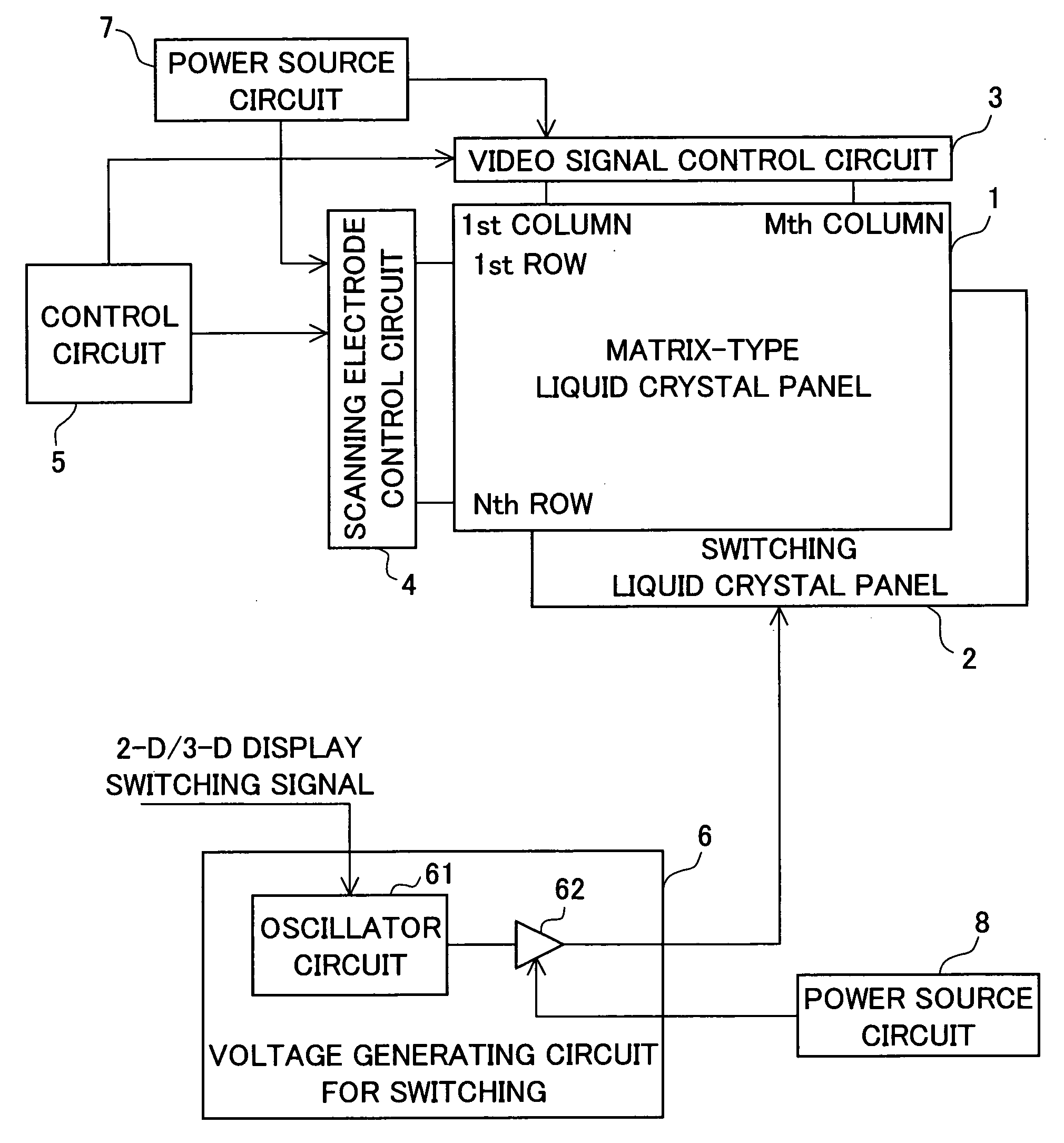
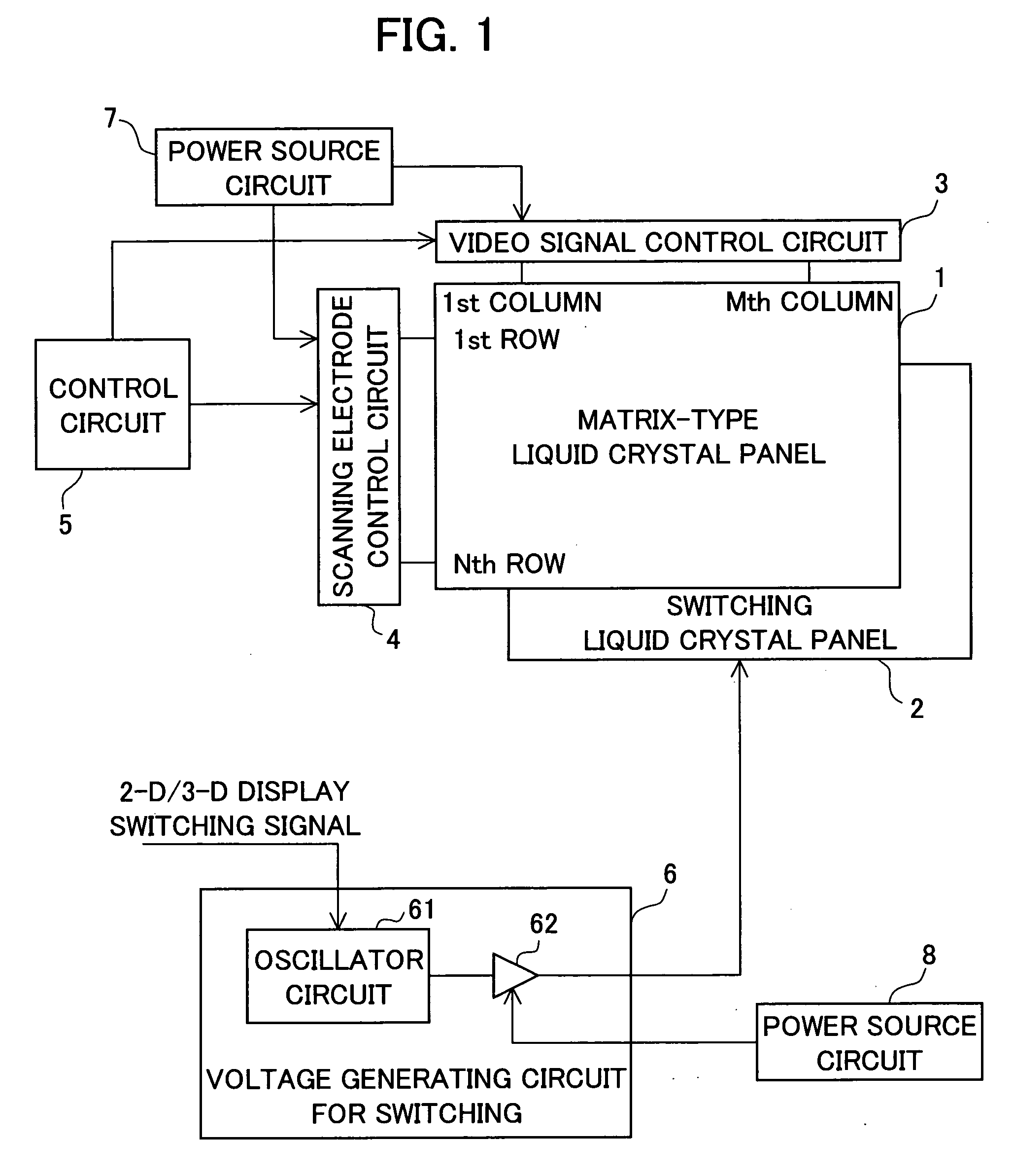
[0052]FIG. 1 is a block diagram schematically illustrating an arrangement of the display apparatus of the present embodiment. As illustrated in FIG. 1, the display apparatus of the present embodiment is provided with a matrix-type liquid crystal panel 1, a switching liquid crystal panel 2, a video signal control circuit 3, a scanning electrode control circuit 4, a control circuit 5, a switching voltage generating circuit 6, and power source circuits 7 and 8.

[0053] The matrix-type liquid crystal panel 1 is, e.g., an active matrix type liquid crystal panel. The matrix-type liquid crystal panel 1 is configured such that first (1st) to Nth scanning lines and first (1st) to Mth signal lines are arranged to cross each other (i.e. in a matrix). In each region segmented with the scanning lines and th...

second embodiment

[0078] The first embodiment is arranged such that the vertical display start signal is generated by the control circuit 5 of the matrix-type liquid crystal panel 1, and the inversion timing signal representing the timing of the polarity inversion of the voltage applied on the switching liquid crystal panel 2 is generated by the switching voltage generating circuit 6. That is, the vertical display start signal and the inversion timing signal are generated in different configuration blocks.

[0079] In this arrangement, there is a possibility that a pulse of the vertical display start signal and a pulse of the inversion timing signal would have a time lag, which would be different in each vertical period. In other words, there is a possibility that the inversion point of the inversion of the switching liquid crystal panel 2 would be changed with respect to the vertical display start signal. If the time lag is changed in each vertical period, the bright line or the dark line flows on the...

example 1

[0090] The control circuit 15 generates an inversion timing signal that is in synchronism with a cycle (i.e. vertical cycle) of a vertical display start signal. The control circuit 15 outputs to the switching voltage generating circuit 16 the thus generated inversion timing signal. The control circuit 15 generates both of the vertical display start signal and the inversion timing signal. Therefore, cycles of the vertical display start signal and the inversion timing signal can be the same.

[0091]FIG. 4 illustrates waveforms of the signals and voltages in the present Example.

[0092] As illustrated in FIG. 4, cycles of the vertical display start signal and the inversion timing signal are in synchronism. Thus, polarity of the voltage applied on the switching liquid crystal panel 2 is inverted once in one vertical period. Therefore, the bright line or the dark line appears once on the displayed screen. A number of the bright line or the dark line is less in the present Example than the ...


PUM

PropertyMeasurementUnit
voltageaaaaaaaaaa
polarityaaaaaaaaaa
voltageaaaaaaaaaa

Abstract

A display apparatus according to the present invention is provided with a matrix-type liquid crystal panel and a switching liquid crystal panel, the matrix-type liquid crystal panel and the switching liquid crystal panel assembled together. In the display apparatus, a polarity of a voltage applied on an electrode pair of the switching liquid crystal panel is inverted once in substantially one vertical period or in one or more vertical period. With this arrangement, it is possible to reduce a number of bright line or dark line. This attains display quality improvement and power consumption reduction.

Description

[0001] This Nonprovisional application claims priority under 35 U.S.C. § 119(a) on Patent Application No. 2004 / 067222 filed in Japan on Mar. 10, 2004, the entire contents of which are hereby incorporated by reference. FIELD OF THE INVENTION [0002] The present invention relates to a method of driving (addressing) a display apparatus (for use in OA (Office Automation) apparatus, AV (Audio Visual) apparatus, and the like apparatus) having a structure in which a liquid crystal panel and a matrix-type image display means are assembled together, and to the display apparatus. BACKGROUND OF THE INVENTION [0003] A display apparatus having a structure in which a liquid crystal panel is provided is conventionally well known as one type of matrix-type display apparatus. One example of such a display apparatus is one having a structure in which a dot-matrix-type display apparatus (for example, M-row / N-column active matrix liquid crystal panel) is assembled together with a liquid crystal panel fo...

Claims


Application Information

Patent Timeline
Patent Type & Authority Applications(United States)
IPC IPC(8): G02F1/133G09G3/20G09G3/36H04N13/00
CPCG09G3/003G09G3/3614H04N13/0497H04N13/0411H04N13/0454H04N13/0409H04N13/31H04N13/312H04N13/359H04N13/398
Inventor HADA, AKIHIROIWAMOTO, AKIHISAOHFUKU, KAZUKITAKEUCHI, MASAKAZU
Owner SHARP KK
Why Eureka
Try Eureka