Method for drawing grin lens fiber

a grin lens and fiber technology, applied in the field of starting drawing a grin lens fiber, can solve the problems of requiring a very long time before winding, affecting the quality of cladding, so as to achieve the effect of reducing the amount of time taken from the start of elongation to the start of winding, reducing the cost, and increasing the length after elongation

Active Publication Date: 2016-08-23
TOYO SEIKAN GRP HLDG LTD
View PDF12 Cites 0 Cited by
  • Summary
  • Abstract
  • Description
  • Claims
  • Application Information

AI Technical Summary

Benefits of technology

[0024]According to the present invention, wastage of the preform when drawing of the GRIN lens fiber from the preform is started is reduced and the elongation speed after elongation of the preform has started is increased, thereby allowing the amount of time taken from the start of the elongation to the start of winding to be reduced. Thus, drawing of the GRIN lens fiber can be efficiently performed and the cost can be significantly reduced.

Problems solved by technology

Since the GRIN lens preform is expensive and valuable, this is a significant loss in terms of the cost.
In addition, the preform having the length of 12 to 18 mm weighs about 0.5 to 0.8 g. Thus, a descending speed of the softened part is very slow, and accordingly, it requires a very long time before winding is started.
However, since the silica glass of the GRIN lens includes a dopant (such as titanium or tantalum that causes the GRIN lens to have a refraction index distribution), a change in viscosity relative to a temperature change is comparatively large.
This may cause a fused and elongated portion to be cut or to become too thin to be wound up during heating, thereby wastage of the preform being increased.
The technology disclosed in the above-described Patent Documents 2 and 3 is used to start drawing of an ordinary optical fiber, and is not useful at all when drawing the GRIN lens preform, which is very small compared to the size of the preform of the optical fiber.

Method used


Image

  • Method for drawing grin lens fiber
  • Method for drawing grin lens fiber
  • Method for drawing grin lens fiber

Examples


embodiment

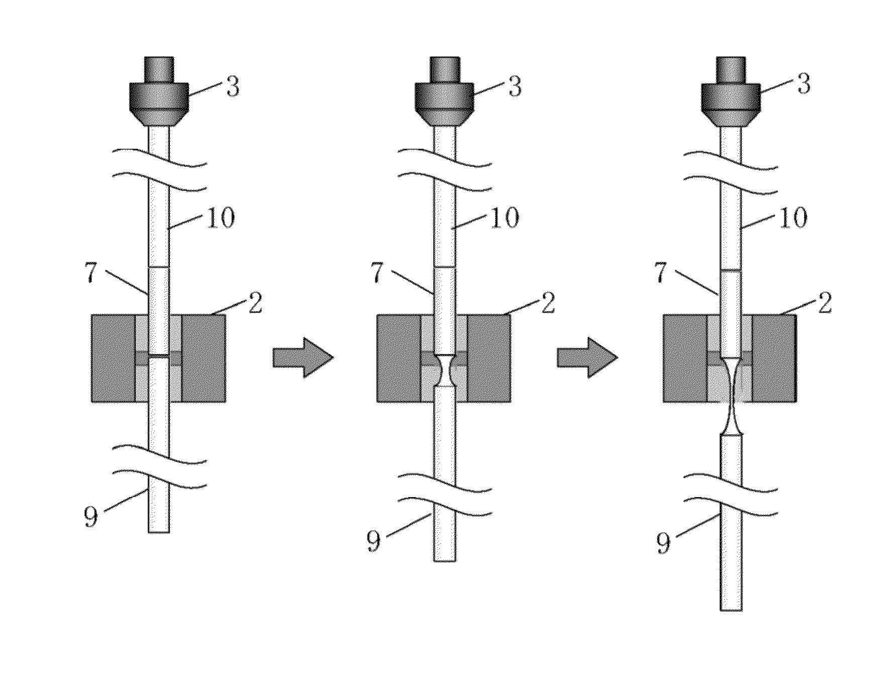
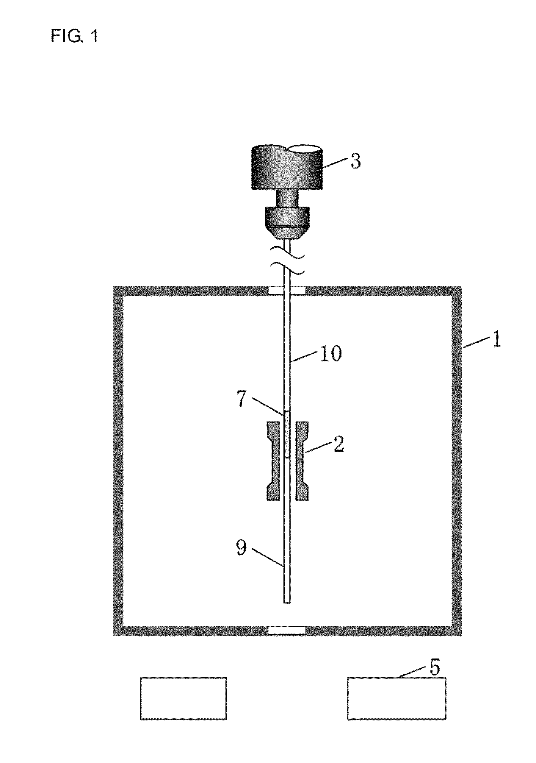
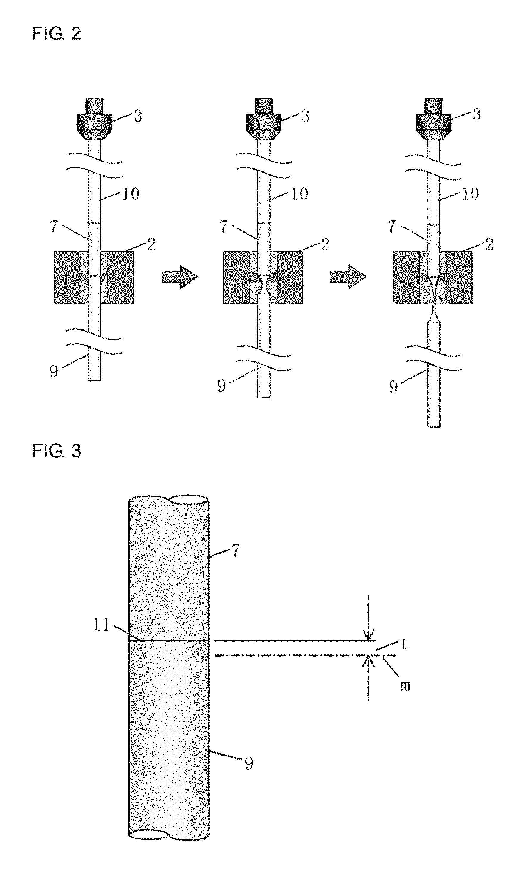
[0041]FIGS. 1 and 4 illustrate equipment for drawing a GRIN lens fiber. The drawing equipment includes a heating furnace 1, a heater 2, an ascending / descending device 3, a winding drum 4, a diameter measuring instrument 5, and an automatic controller 6.

[0042]The heating furnace 1 is a very high temperature vertical pipe furnace, the temperature of which can be increased up to 2100° C.

[0043]The winding drum 4 includes a horizontal movement mechanism that prevents a turn of a fiber from overlapping another turn of the fiber. In the present embodiment, a drawn GRIN lens fiber is directly wound using a winding drum 4. By controlling a rotation speed of the winding drum, a drawing speed is controlled. A capstan roller may be provided before the winding drum in order to control the drawing speed by controlling a rotation speed of the capstan roller.

[0044]Above the heating furnace 1, the ascending / descending device 3 is provided in order to hold and move up and down a preform 7.

[0045]A sil...


PUM

PropertyMeasurementUnit
weight weighsaaaaaaaaaa
lengthaaaaaaaaaa
lengthaaaaaaaaaa

Abstract

When drawing of a GRIN lens from a preform is started, wastage of the preform is reduced and the amount of time taken from the start of elongation of the preform to the start of winding is reduced. A preform, to a lower end of which a weight formed of silica is fused, is set in a heating furnace, and drawing of the preform is started by heating a fused portion where the preform and the weight are fused to each other. This can reduce wastage of the preform. Since an elongation speed of the preform is increased by the weight of the weight, the amount of time taken from the start of the elongation of the preform to the start of winding can be decreased.

Description

BACKGROUND OF THE INVENTION[0001](1) Field of the Invention[0002]The present invention relates to a method for starting drawing of a GRIN lens fiber from a preform in a method for drawing the GRIN lens fiber, and in particular, relates to a method for reducing time taken to start drawing and decreasing an amount of wasted preform.[0003](2) Description of Related Art[0004]A so-called GRIN fiber lens is a cylindrical graded index lens (GRaded INdex lens) having a refraction index distribution within a glass so as to bend a traveling direction of light, thereby realizing the function of the lens. Typically, the GRIN lens is cut into pieces of less than about 1 mm, each of which is welded to the tip of an optical fiber, and used in a variety of applications in optical systems for optical communications. Today, there is a demand for GRIN lenses having high NA (numerical aperture). Preforms of such GRIN lenses are fabricated in a sol-gel method as disclosed in Patent Document 1 below and ...

Claims


Application Information

Patent Timeline
Patent Type & Authority Patents(United States)
IPC IPC(8): C03B37/025C03B37/027G02B6/028G02B3/00
CPCC03B37/02772G02B6/028C03B2203/26C03B2205/47G02B3/0087C03B37/02G02B3/00
Inventor FUKUDA, TOSHIAKI
Owner TOYO SEIKAN GRP HLDG LTD
Why Eureka
Try Eureka