Laser cutting method and laser cutting device

a laser cutting and laser cutting technology, applied in metal-working equipment, welding equipment, manufacturing tools, etc., can solve the problems of inability to secure, and excessive melting of workpieces, so as to suppress the occurrence of abrupt melting and suppress the occurrence of scratching of workpieces

Inactive Publication Date: 2016-09-06
NISSAN TANAKA CORP
View PDF17 Cites 10 Cited by
  • Summary
  • Abstract
  • Description
  • Claims
  • Application Information

AI Technical Summary

Benefits of technology

[0027]According to the above-mentioned laser cutting method and laser cutting device, in the vicinity of the end point of the laser cutting and the corner section, it is possible to suppress the occurrence of abrupt melting due to excessive heating of the remaining margin, and suppress the occurrence of scratching in the workpiece.BRIEF DESCRIPTION OF INVENTION
[0028]FIG. 1 is a view showing a schematic configuration of a laser cutting device according to an embodiment of the present invention.
[0029]FIG. 2 is a schematic block diagram for describing an operation of the laser cutting device according to the embodiment of the present invention.
[0030]FIG. 3 is a schematic view showing an action of the laser cutting device according to the embodiment of the present invention.
[0031]FIG. 4 is a view showing an effective range of a first moving speed of the laser cutting device according to the embodiment of the present invention.
[0032]FIG. 5A is a view for describing a cutting method in the vicinity of a cutting end point in laser cutting of the related art.

Problems solved by technology

However, for example, when oxygen is used as the cutting gas such as when cutting a soft steel material, depending on the cut shape or material and a surface state, an excessively wide range on the workpiece may reach a high temperature, and the workpiece may be excessively melted such that a desired shape in the vicinity of a cutting end point cannot be secured.
However, when the cutting is performed while the micro joint remains, the micro joint should be separately cut, and the number of cutting processes and the total cutting costs are increased.
Meanwhile, in the cutting relief, scratching is likely to occur in the vicinity of the end point of the cutting.

Method used


Image

  • Laser cutting method and laser cutting device
  • Laser cutting method and laser cutting device
  • Laser cutting method and laser cutting device

Examples


Embodiment Construction

[0039]Hereinafter, an embodiment of the present invention will be described with reference to the accompanying drawings.

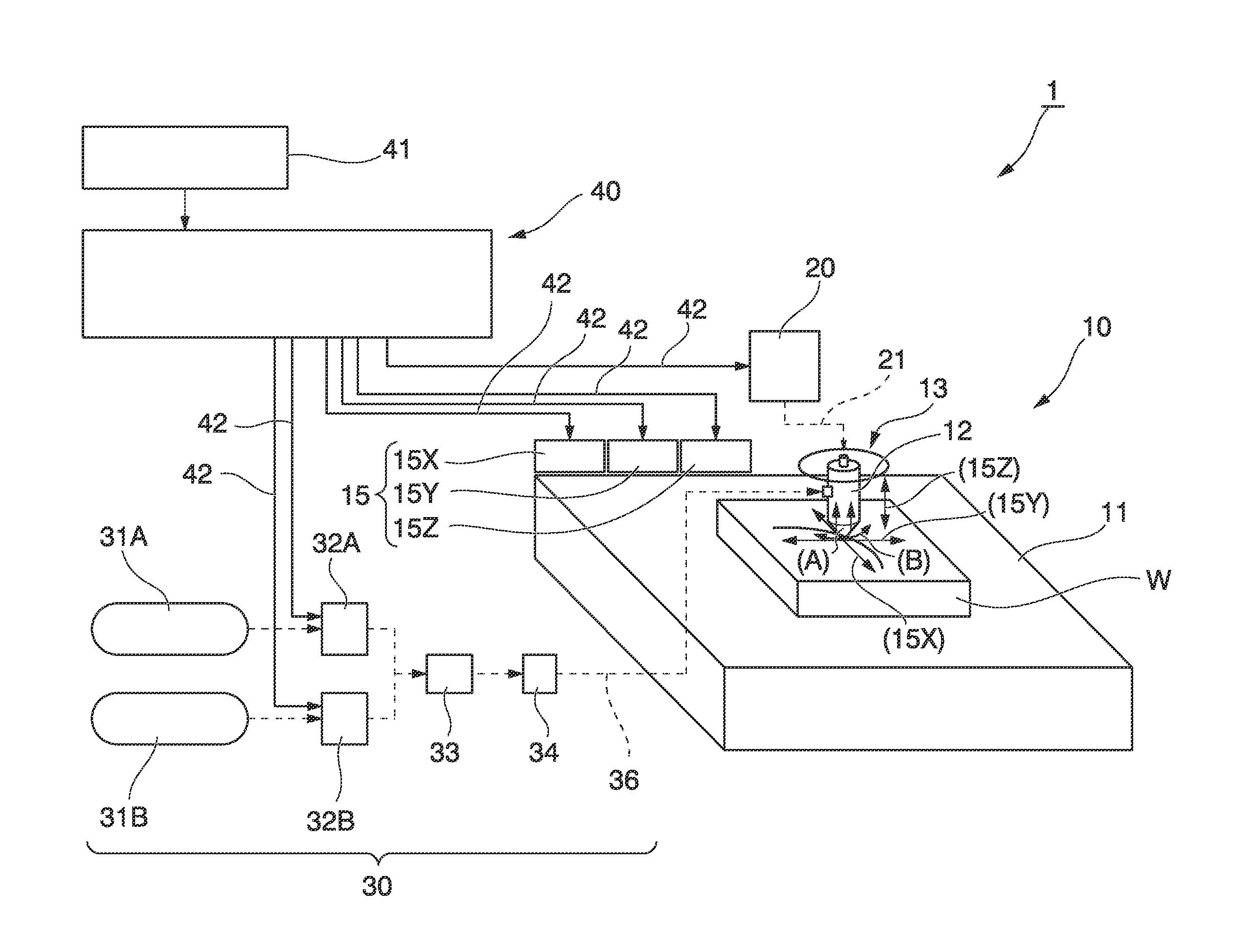
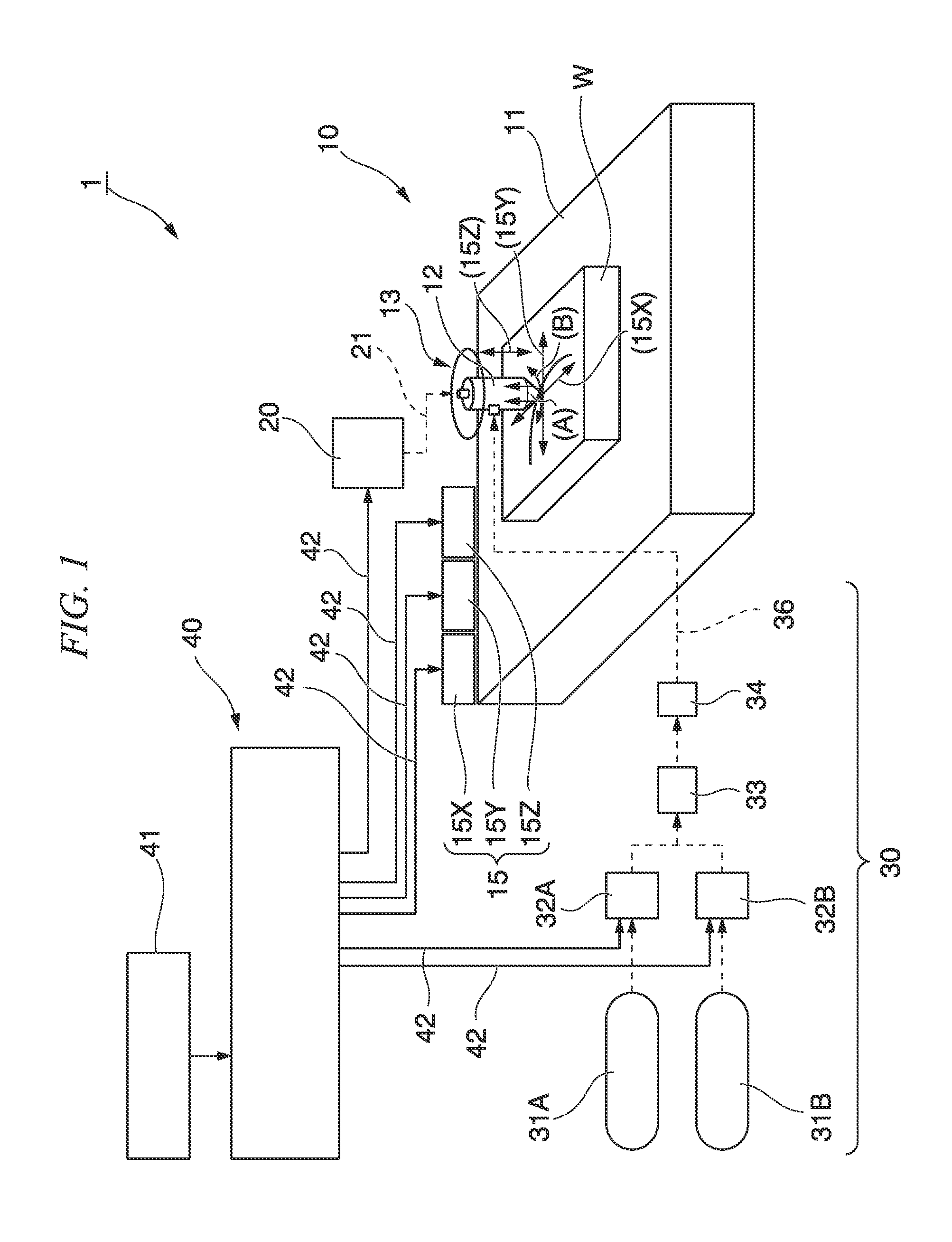
[0040]FIG. 1 is a view schematically showing a laser cutting device according to an embodiment of the present invention. Reference numeral 1 designates the laser cutting device.

[0041]The laser cutting device 1 includes a laser machining apparatus main body 10, a laser oscillator 20, a gas supply unit 30, and a control unit 40. The workpiece W is covered with a cutting gas injected from the gas supply unit 30 while a laser beam is radiated to a workpiece W by a laser nozzle 12 installed at the laser machining apparatus main body 10, and the workpiece W is cut by moving the laser nozzle 12 with respect to the workpiece W.

[0042]The laser machining apparatus main body 10 includes, for example, a surface plate 11 on which the workpiece W is placed, the laser nozzle 12, a nozzle holding unit 13 configured to hold a nozzle hole of the laser nozzle 12 toward a predetermine...


PUM

PropertyMeasurementUnit
thicknessaaaaaaaaaa
relative moving speedaaaaaaaaaa
speedaaaaaaaaaa

Abstract

A laser cutting device includes a control unit which sets a steady oxygen concentration, a moving speed of a laser nozzle and laser beam steady control conditions based on a material and a plate thickness of the workpiece, decreases the moving speed of the laser nozzle to a first setting speed when the laser nozzle arrives a first setting position in front of an end point of a cutting trajectory, and decreases a relative moving speed of the laser nozzle to a second setting speed by varying the oxygen concentration of the cutting gas and the control condition of the laser beam when the laser nozzle arrives at a second setting position.

Description

CROSS REFERENCE TO RELATED APPLICATIONS[0001]This application is the national stage of International Application No. PCT / JP2012 / 076823, filed Oct. 17, 2012, entitled, “Laser Cutting Method And Laser Cutting Device,” which claims the benefit of priority of Japanese Patent Application No. 2011-241464, filed Nov. 2, 2011, the contents of which are incorporated herein by reference in their entirety.TECHNICAL FIELD[0002]The present invention relates to a laser cutting method and a laser cutting device capable of injecting a cutting gas and cutting a workpiece while radiating a laser beam to the workpiece.BACKGROUND ART[0003]In laser cutting, a cutting gas flows around a laser beam, a workpiece is melted by energy of the laser beam radiated to the workpiece and oxidation reaction energy between the workpiece and the cutting gas, and a melted metal is discharged by the kinetic energy of the cutting gas.[0004]When the workpiece is cut by such laser cutting, an end point of the laser cutting...

Claims


Application Information

Patent Timeline
Patent Type & Authority Patents(United States)
IPC IPC(8): B23K26/08B23K26/38B23K26/14B23K26/00
CPCB23K26/14B23K26/08B23K26/0869B23K26/0884B23K26/1435B23K26/38B23K26/0853
Inventor NUMATA, SHINJIKAMIKIHARA, HIROTAKASANO, YOSHIMI
Owner NISSAN TANAKA CORP
Why Eureka
Try Eureka