Two stage fluid catalytic cracking process and apparatus

a fluid catalytic cracking and fluid technology, applied in catalytic cracking, lighting and heating apparatus, hydrocarbon oil treatment, etc., can solve the problems of reducing the gasoline yield of oil refiners worldwide, affecting the selectivity of middle distillates, and accumulating refractory materials in the system, so as to maximize the light olefins and maximize the selectivity

Active Publication Date: 2016-09-06
INDIAN OIL CORPORATION
View PDF12 Cites 7 Cited by
  • Summary
  • Abstract
  • Description
  • Claims
  • Application Information

AI Technical Summary

Problems solved by technology

Varying supply-demands for distillate fuels and light olefins like propylene and ethylene, are affecting the oil refiners worldwide.
Also, in Europe for instance due to the growth of diesel consumption there are several refineries, which are attempting to reduce their gasoline yield because of imbalance over supply.
The recycle of heavier bottom fractions from the common fractionator results in the buildup of refractory material in the system.
The main disadvantage of this process is that the catalyst activity reduces considerably, after passing through one riser and the same catalyst may not be effective in cracking reactions taking place in the second riser.
In all the above mentioned two stage systems employing dual riser reactors, problems like back mixing and higher coke yield persist.
CN101210191A proposes a similar configuration where the downer and riser reactors are connected in series wherein the hydrocarbon feed is introduced into the inlet of the downer reactor for catalytic cracking at a Catalyst / Oil ratio of 5-40 and operating temperature of 480-660° C., the entire reactor effluent is further contacted in a riser with the spent catalyst from the downer at a Catalyst / Oil ratio of 10-35 and operating temperature of 450-650° C. The disadvantages of such systems are (i) significant reduction in conversion in the second reactor due to use of partially deactivated catalyst from the first reactor; (ii) cracking of the desired product fractions formed in the first reactor.
Furthermore, simultaneous maximization of middle distillates and light olefins is not possible using such configuration.
In the above mentioned process scheme, same catalyst is being used in the two reaction zones, namely downer and riser; this makes it less flexible for the processing of feed stocks of widely varying quality.

Method used


Image

  • Two stage fluid catalytic cracking process and apparatus
  • Two stage fluid catalytic cracking process and apparatus

Examples


example 1

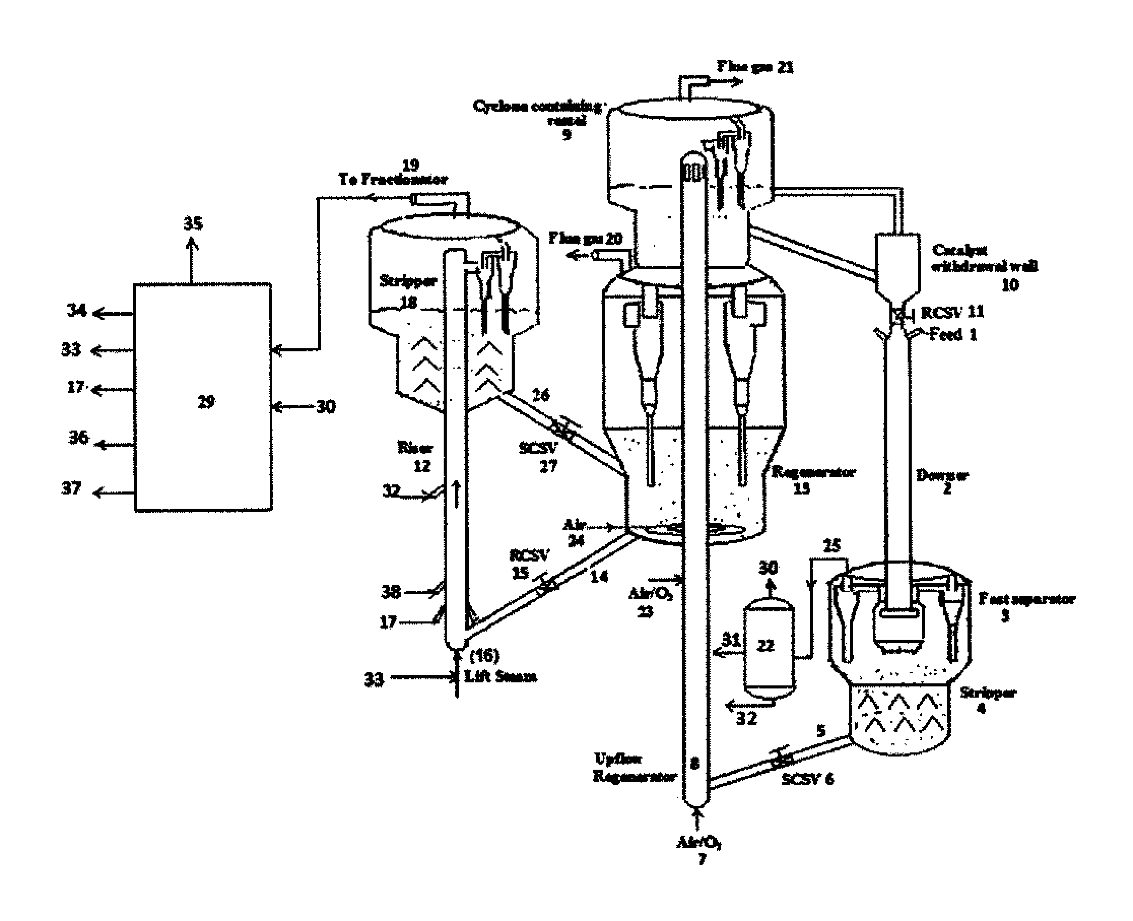
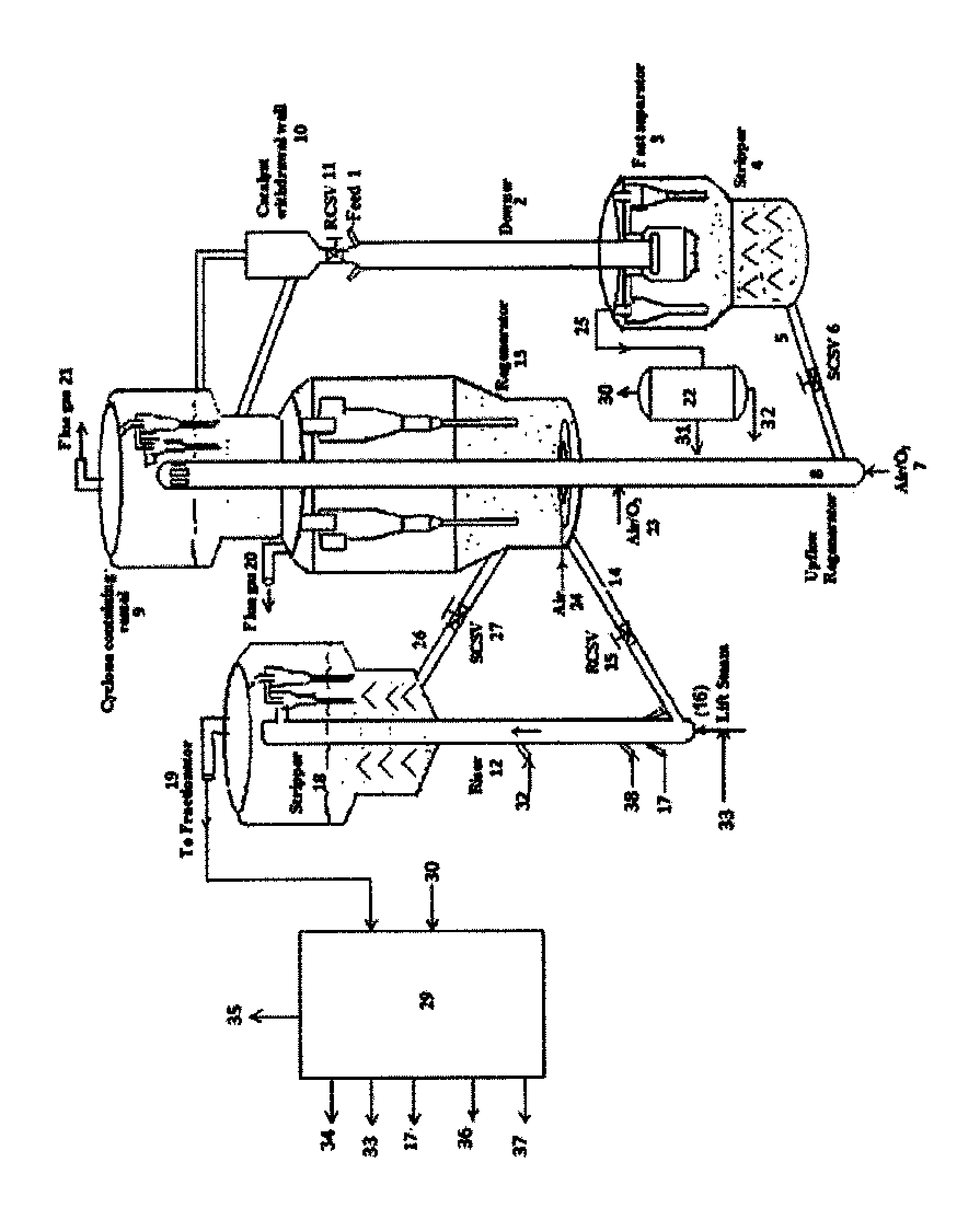
[0052]The invented process can be used for the maximization of propylene alone, using a process scheme described as under. Fresh feed is contacted at the entry of the first flow reactor of short contact time with hot circulating catalyst coming from the regenerator, where the cracking reactions take place providing a contact time in the range of 0.2-0.5 seconds. The reaction temperature is around 550-650° C. with catalyst to hydrocarbon feed ratio in the range of 10-35. The first reactor effluent fraction, boiling above 150° C. which are separated using first fractionator and hydrocarbon fractions, naphtha and C4 from second product separation section are passed through the second flow reactor, operating at a temperature of 550-650° C. with a hydrocarbon residence time below 3 sec and catalyst to oil ratio of 10-25. A highly active Y zeolite catalyst containing 5-30 wt % of shape selective pentasil zeolite based catalyst can be used in the first flow reactor, and a highly active Y z...

example 2

[0053]The invented process can be used for the maximization of gasoline alone, using a process scheme described as under. Fresh feed is contacted at the entry of the first flow reactor of short contact time with hot circulating catalyst coming from the regenerator, where the cracking reactions take place providing a contact time in the range of 0.5-1 seconds. The reaction temperature is around 500-580° C. with catalyst to hydrocarbon feed ratio in the range of 515. The first reactor effluent fraction, boiling above 210° C., are separated using a first fractionator, are then passed through the second flow reactor, operating at a temperature of 500-560° C., with a hydrocarbon residence time of 1-3 sec and catalyst to oil ratio of 5-12. REUSY / USY-Zeolite based catalysts with 2-10 wt % of shape selective pentasil zeolite based catalyst can be used in both the flow reactors.

example 3

[0054]The invented process can be used for the maximization of middle distillates alone, using a process scheme described as following. Fresh feed is contacted at the entry of the first flow reactor of short contact time with hot circulating catalyst coming from the regenerator where the cracking reactions take place providing a contact time below 2 seconds. The reaction Temperature is around 450-520° C. with catalyst to hydrocarbon feed ratio in the range of 4-8. The first reactor effluent fraction boiling above 370° C. are separated using a first fractionator are then passed though the second flow reactor, operating at a temperature of 470-530° C., with a hydrocarbon residence time below 5 sec and catalyst to oil ratio of 4-10. A catalyst with high matrix content can be used in the first flow reactor and low active catalyst containing 5-30 wt % of large pore bottom selective active material, can be used in the second flow reactor.

[0055]In one embodiment, a part of the unconverted ...


PUM

PropertyMeasurementUnit
pore sizeaaaaaaaaaa
temperatureaaaaaaaaaa

Abstract

A two stage Fluid Catalytic Cracking process and an apparatus for simultaneous production of light olefins such as ethylene and propylene and middle distillate range hydrocarbons, wherein a first flow reactor, preferably a downer and a second flow reactor, preferably a riser are operating at varying reaction severities using different catalyst systems with the regenerated catalyst entering the reactors inlet through independent regenerators. Mild cracking of the fresh feedstock is carried out in the first flow reactor of short residence time and the effluent of first flow reactor is separated in an intermediate separator / fractionator followed by re-cracking of the C4 hydrocarbons and naphtha range hydrocarbons, preferably C5-150° C. from the second product separation section and unconverted hydrocarbons (370° C.+) of first flow reactor, in the second flow reactor at higher severity employing different catalyst system.

Description

FIELD OF THE INVENTION[0001]This invention relates to Fluid Catalytic Cracking (FCC) of heavy hydrocarbons into lighter fractions with a fluidized stream of solid catalyst. This invention particularly relates to an improved process and apparatus for simultaneous maximization of light olefins including ethylene and propylene and middle distillates, with flexibility of alternate mode of operation for maximization of gasoline.BACKGROUND OF THE INVENTION[0002]Varying supply-demands for distillate fuels and light olefins like propylene and ethylene, are affecting the oil refiners worldwide. Several drivers, like increasing gap between demand and supply for propylene are affecting the growing need for the production of the same by Fluid Catalytic Cracking. The need for propylene is growing faster than that of ethylene, while on the other hand the co-production of propylene from steam crackers (˜70% of supply) is expected to decline as plants are optimized to produce higher-value ethylene....

Claims


Application Information

Patent Timeline
Patent Type & Authority Patents(United States)
IPC IPC(8): C10G51/00C10G51/02C10G11/18
CPCC10G51/026C10G11/18C10G2300/207C10G2300/301C10G2300/4093C10G2300/807C10G2400/02C10G2400/20
Inventor PRADEEP, PONOLY RAMACHANDRANMUKTHIYAR, SADHULLAHSAIDULU, GADARIBHATTACHARYYA, DEBASISSATHEESH, VETTERKUNNEL KUMARAN
Owner INDIAN OIL CORPORATION
Why Eureka
Try Eureka