Targeting system for use with x-ray machines

Active Publication Date: 2016-09-13
NANCE KIRBY +1
View PDF5 Cites 21 Cited by
  • Summary
  • Abstract
  • Description
  • Claims
  • Application Information

AI Technical Summary

Benefits of technology

[0012]The laser light sources installed on the band are centered 90° from each other. When the power supply is activated, a visible fan shaped beam of coherent light is emitted from each of the two laser assemblies. Because of the 90° displacement of the laser assemblies, the two fan-shaped beams cross each other to form an easily viewable target area. The laser assemblies are covered with a housing having two openings: 1) an opening through which the laser beam's coherent light is emitted, and 2) an opening for accessing a control arm to adjust the aim of the laser beam. The control arm at the side of a housing is maneuverable by an operator to fine tune the laser aiming system so to locate

Problems solved by technology

The drawback with McNeirney is that the device must be removed before the patient is in place, and because of this, real-time information as to the location of the x-ray field's center cannot be known during the procedure and harm could result if the center shifts for some reason.
Among the drawbacks with the Wang device is that, during a procedure, the reflector is positioned below and to the side of the patient being x-rayed.
If the patient is large, the reflector may be blocked from receiving the projected laser light.
Further, the proximity of the reflector to the patient and x-ray technician is such that it can easily be dislodged or misaligned by the patient or technician.
Also, use of the Wang device involves a significant amount of training before a technician can reliably set it up and use it.
Drawbacks of the apparatus are that it is designed for flooding light into a general area, not targeting a point; the large number of components an operator must install with respect to the optical elem

Method used


Image

  • Targeting system for use with x-ray machines
  • Targeting system for use with x-ray machines
  • Targeting system for use with x-ray machines

Examples


Embodiment Construction

[0024]The following detailed description illustrates the invention by way of example and not by way of limitation. This description clearly enables one skilled in the art to make and use the invention, and describes several embodiments, adaptations, variations, alternatives and uses of the invention, including what is presently believed to be the best mode of carrying out the invention. Additionally, it is to be understood that the invention is not limited in its application to the details of construction and the arrangement of components set forth in the following description or illustrated in the drawings. The invention is capable of other embodiments and of being practiced or carried out in various ways. Also, it will be understood that the phraseology and terminology used herein is for the purpose of description and should not be regarded as limiting.

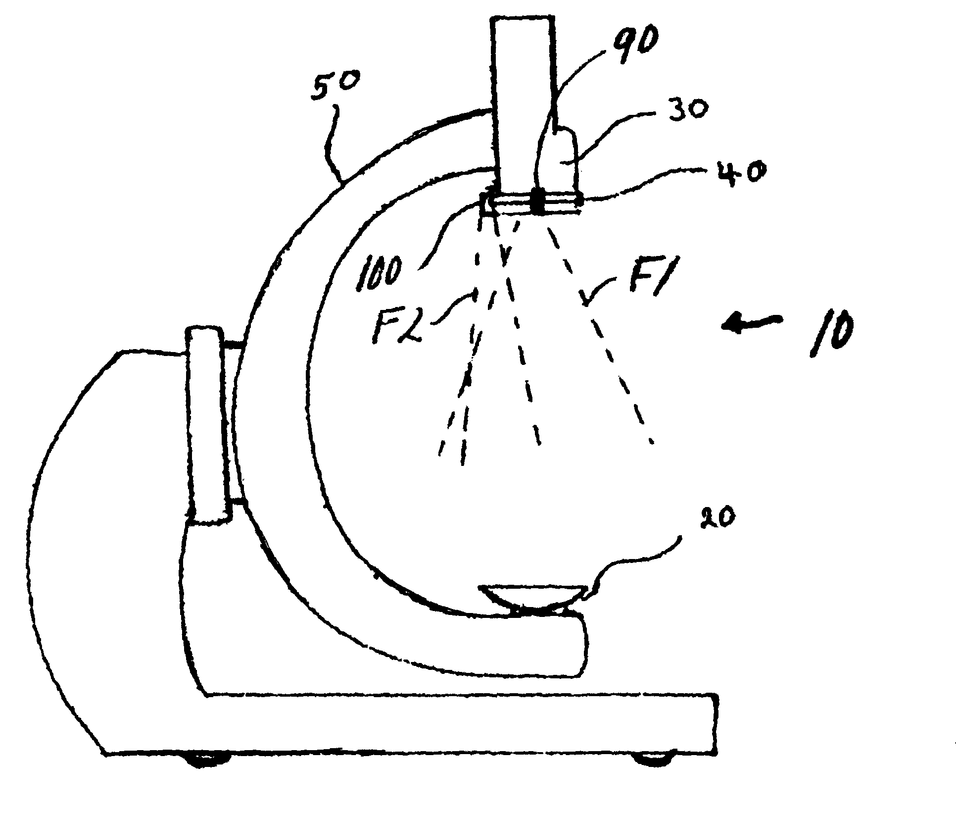
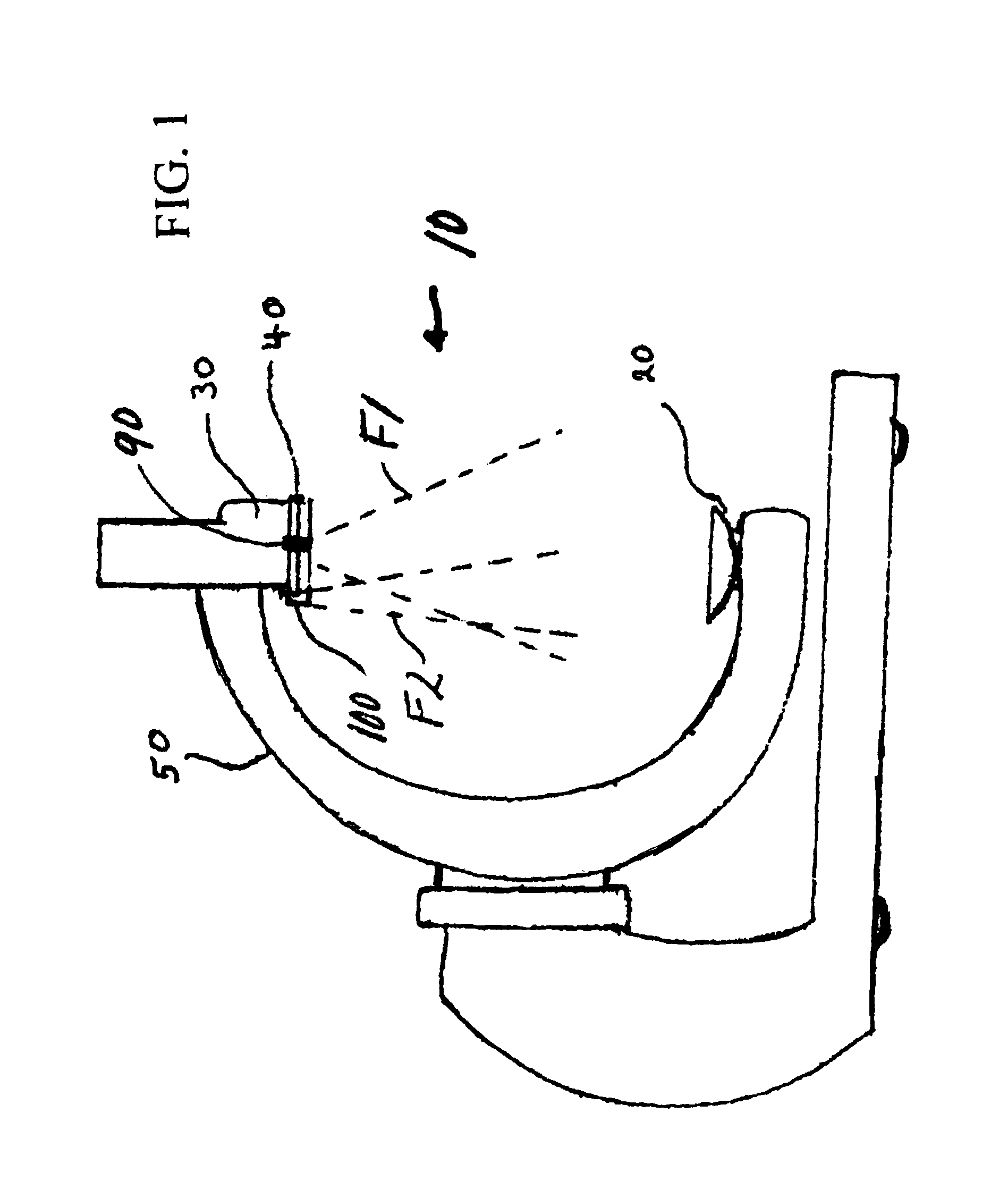
[0025]Referring to the drawings, the present invention is directed to a laser aiming system for use in designating a target area a...


PUM


Abstract

Apparatus for use with a C-arm type x-ray unit (10) to locate and center an x-ray target area. The unit has an x-ray emitter (20) located at one end of a C-arm (50) and an x-ray receptor located at the other end of the C-arm. A ring-shaped band (45) adjustably fits around an outer end of the x-ray receptor. A first laser light source (90) and a second laser light source (100) are carried on the band in a predetermined orientation to each other. The laser light sources each project a fan shaped laser light into the target area between the x-ray emitter and the x-ray receptor. The beams are adjusted to determine a center of the target area through which x-rays are propagated when a patient is positioned in the x-ray unit for a procedure to be performed.

Description

BACKGROUND OF THE INVENTION[0001]This invention relates to x-ray positioning systems; and, more particularly, to a dual laser apparatus and method for aiming at and targeting the center of an x-ray field for subsequent use in performing medical diagnostics or procedures involving the use of an x-ray machine.[0002]In setting up for a procedure involving x-rays, it is important to properly align the equipment so that when x-rays are directed at a patient's or subject's body by an x-ray machine, they are directed at the correct part of a person's anatomy. This prevents potentially harmful radiation for being directed at wrong parts of the person's body, or inadvertently at others who may be present for the procedure. There are a number of currently known procedures for affecting proper alignment, and while each may work to accomplish their goal, each has certain drawbacks.[0003]In U.S. Pat. No. 6,267,502 to McNeirney, there is disclosed a device to assist alignment of an x-ray beam cen...

Claims


Application Information

Patent Timeline
IPC IPC(8): A61B6/00A61B6/08
CPCA61B6/587A61B6/08A61B6/4441
Inventor NANCE, KIRBYNANCE, KAREN
Owner NANCE KIRBY
Why Eureka
Try Eureka