
Multi-band photodiode sensor

a photodiode sensor and multi-band technology, applied in the field of multi-band photodiode sensors, can solve the problems of inability to deploy wired sensors, change leaf architecture, and measurement concerning thermal bands, so as to reduce false positive irrigation scheduling, increase plant yield, and improve efficiency and cost-effective irrigation

Active Publication Date: 2016-09-27
SOUTHERN ILLINOIS UNIVERSITY +1
View PDF40 Cites 32 Cited by
  • Summary
  • Abstract
  • Description
  • Claims
  • Application Information

AI Technical Summary

Benefits of technology

The patent describes a new sensor that can measure the temperature and reflectance of a plant's canopy in multiple bands, storing the data in a microprocessor and transmitting it wirelessly to a receiver at a remote location. The sensor is designed to help manage irrigation more efficiently, reducing false positive scheduling and increasing yields per unit of water applied.

Problems solved by technology

However, the technical note did not address measurements concerning the thermal band.
Measuring crop canopy surface radiometric temperature remotely using such an IRT has the disadvantage of also measuring soil background reflectance early in a growing season when crop canopy cover is limited, and possibly throughout the growing season in the case of row crop planting (for sensor view angles that are nadir or substantially parallel to crop rows), missing plants, and changing leaf architecture from loss of turgor pressure.
Furthermore, because it is impractical to deploy wired sensors along a sprinkler lateral whose length is commonly a quarter-mile or longer, wireless sensing devices are needed to commercialize the integration of multi-band radiometers onto a moving sprinkler system (O'Shaughnessy and Evett, 2010, ibid).
Also, most radiometers used in agricultural applications are deployed such that the cropped surface is viewed at an oblique angle, resulting in the sensor footprint having an elliptical shape.

Method used


Image

  • Multi-band photodiode sensor
  • Multi-band photodiode sensor
  • Multi-band photodiode sensor

Examples


Embodiment Construction

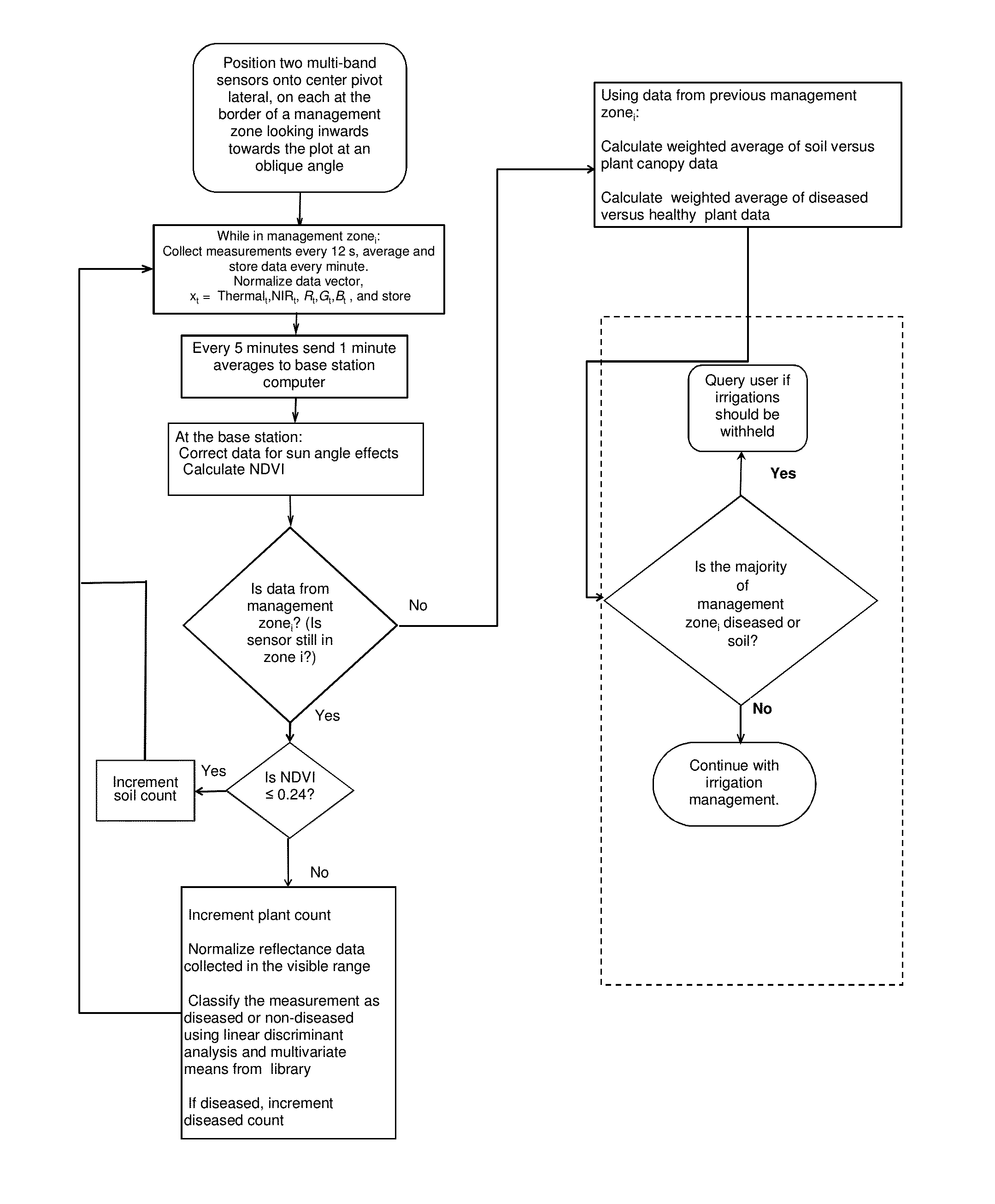
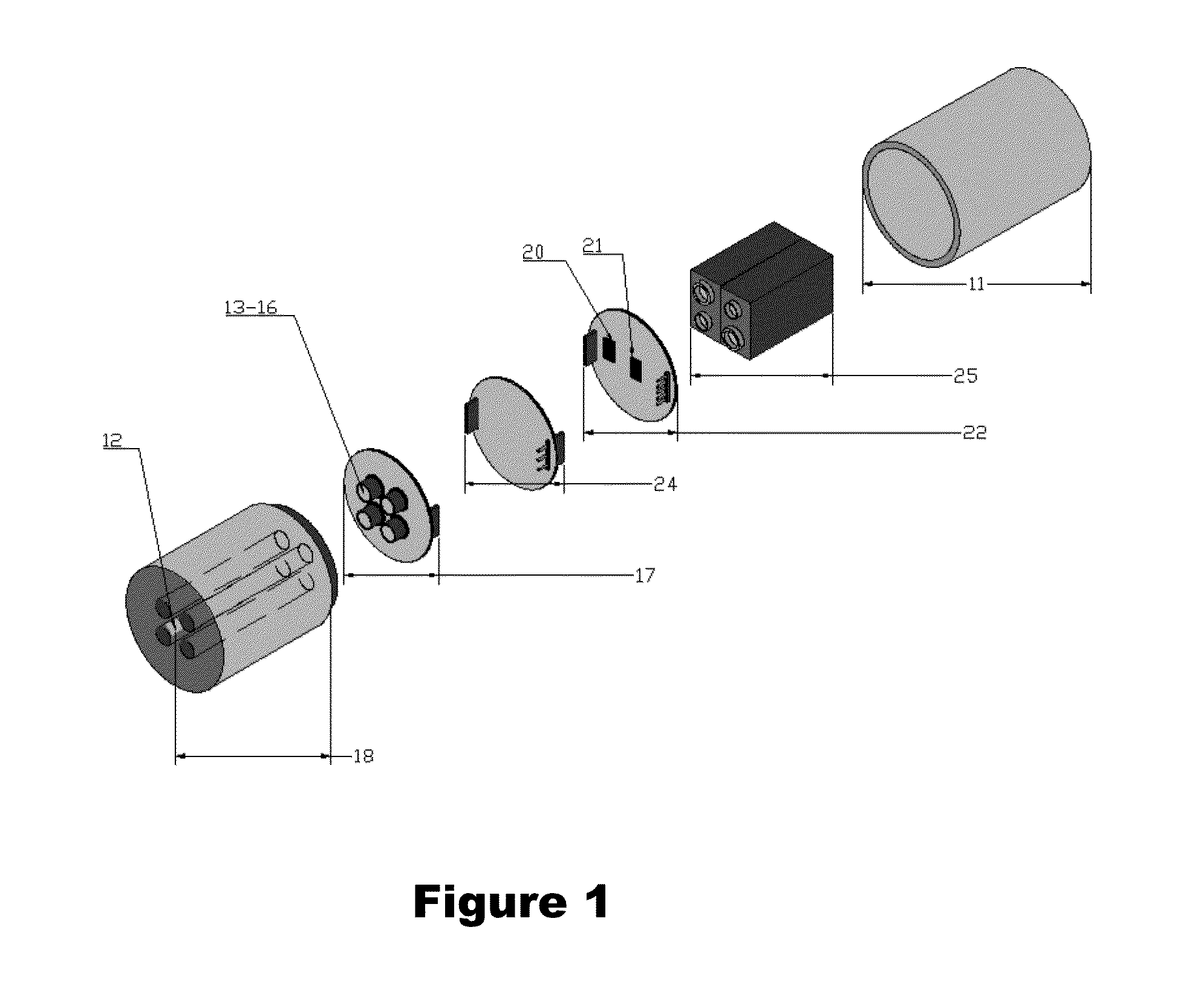
[0029]The multi-band sensor described herein was designed as a single, self-contained unit with multiple detectors or sensors for making measurements of plant canopy temperature and spectral reflectance in the NIR, red, green and blue bands, storing the data in a microprocessor, and wirelessly transmitting the data to a receiver at a remote location. As shown in FIG. 1, the multi-band sensor includes a housing or casing (11) of sufficient size as to contain all of the components therein. The housing may be constructed from a variety of materials, but should be weather-proof to prevent damage to the detectors therein. In a preferred embodiment, the housing is constructed from two or more pieces of rigid sunlight resistant plastic for ease of access.

[0030]Plant canopy (or soil) surface temperature is effectively measured with an infrared thermometer or IRT (12), which is sensitive to infrared (IR) radiation in the thermal range, between about 5 to 14 μm. A variety of infrared thermome...


PUM


Abstract

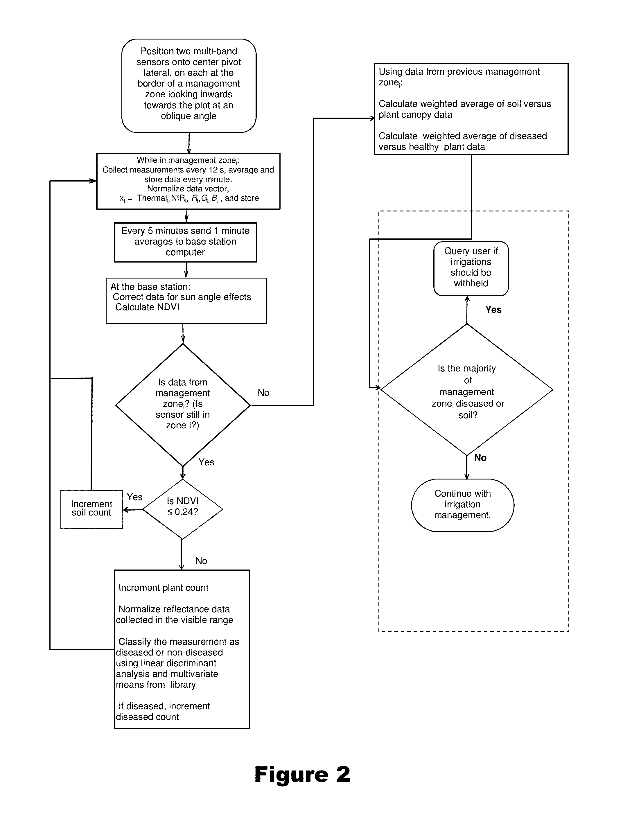
Plant canopy temperature and multi-spectral reflectance are measured with a wireless multi-band sensor, and the temperature data are qualified and the spectral reflectance measurements are classified. The multi-band sensor includes sensors for measuring plant canopy temperature radiation and spectral reflectance over five bands, a microprocessor to receive and store measured data, and a wireless transmitter for transmitting data from the microprocessor to a remote receiver, all enclosed within a single housing. The data are used to detect variations in spectral signature due to plant stress (e.g., disease, water stress) and due to soil background and to qualify temperature data accordingly. The data provide information for decision support algorithms related to the initiation of automatic irrigation scheduling as a function of crop canopy cover, qualification of temperature data used in automatic irrigation scheduling algorithms, and detection of diseased crops for the purpose of withholding irrigations when yield potential is compromised.

Description

CROSS-REFERENCE TO RELATED APPLICATIONS[0001]This application claims the benefit under 35 U.S.C. 1.19(e) of U.S. provisional 61 / 703,846, filed Sep. 21, 2012, the contents of which are incorporated by reference herein.BACKGROUND OF THE INVENTION[0002]1. Field of the Invention[0003]The invention is drawn to a method and apparatus for measuring plant canopy temperature and multi-spectral reflectance and managing irrigation.[0004]2. Description of the Prior Art[0005]Multi-band radiometers are optical sensors, typically consisting of two or more photodiode detectors or charge coupled devices, which produce electrical current that is proportional to the light energy to which they are exposed. The incoming light is filtered to a specific wavelength in the visible and near infrared ranges. These sensors are typically remote (as opposed to contact) sensors used as hand-held or vehicle-mounted instruments to remotely assess plant biophysical properties such as leaf area and ground cover (Vaes...

Claims


Application Information

Patent Timeline
Patent Type & Authority Patents(United States)
IPC IPC(8): G01J5/00A01G9/24A01G25/16G01J5/02
CPCA01G25/167G01J5/02A01G7/00G01J3/36G01J3/42G01J5/007G01J5/025G01J5/026G01J5/028G01J5/04
Inventor O'SHAUGHNESSY, SUSAN A.EVETT, STEVEN R.HEBEL, MARTIN A.COLAIZZI, PAUL D.
Owner SOUTHERN ILLINOIS UNIVERSITY
Learn More