
Suspended fluid dispenser system and apparatus

a fluid dispenser and system technology, applied in the direction of dispensers, liquid transfer devices, holders, etc., can solve the problems of product waste practically inevitable, pump mechanical failure and inefficiency, and the inability to provide a dispensing fluid container with a pump- or siphon-action fluid outlet is relatively significantly more expensive, so as to achieve the effect of quick and clean dispense of viscous fluid comestibles

Active Publication Date: 2016-10-11
HURWITZ SARAH DEBORAH DR
View PDF33 Cites 6 Cited by
  • Summary
  • Abstract
  • Description
  • Claims
  • Application Information

AI Technical Summary

Benefits of technology

"The present invention is a novel and useful mountable and rotatable suspended fluid dispenser that can be easily attached to a variety of fixtures and used in close proximity to the area of use. The invention allows for easy one-handed operation, reduces the risk of spills and clean-up, and improves advertising value. The invention also provides a solution for storing and dispensing powders and viscous fluids that can be easily attached to fixtures and suspended overhanging surfaces. The coupler can be rotated in a controllable and incremental manner to elevate or lower the fluid outlet with respect to the fluid level in the container. The invention is simple to use, efficient, and can be adapted to a variety of fixture shapes and sizes. It also allows for the attachment of a fluid container to a fixture without interfering with the fixture's normal use. The invention is ideal for use in kitchens and bathrooms where fixtures are commonly found."

Problems solved by technology

With respect to cost, providing a dispensing fluid container with a pump- or siphon-action fluid outlet is relatively significantly more expensive than providing a fluid container with a gravity-dependent fluid outlet.
Moreover, a pump can suffer from mechanical failure and be inefficient in that most are unable to extract some significant portion of fluid from a nearly-emptied container, especially if the fluid is very viscous.
Furthermore, product waste is practically inevitable as the contents are gradually used since some product often clings to the bottom lower sides of the container interior.
Unfortunately, that requires that the tube be rested on a flat surface, usually a kitchen, sink or bath countertop, tabletop or ledge, thus adding to clutter, increasing potential for spills and residual drips, soiling and using some of the most valuable and heavily used real estate in any home or work environment.
In the alternative, product is wasted by those not desirous of employing economizing strategies.
In situations where a fluid dispenser will get heavy use, such as in a public restroom or dining hall, the risk of passing infection increases where other people must handle the container at its dispensing point and along its outer side surfaces of the dispenser sufficiently firmly to maintain a grip and invert the dispenser.
Unfortunately, such devices often have flow-rate control and leakage issues, resulting almost inevitably in spillage on the counter or articles below the dispenser.
Frequently the containers can't be pumped dry as they can't get the last bit at the bottom.
Furthermore, pumps are often difficult to control and users often spill condiment on the countertop instead of on the food, adding to maintenance.
Unfortunately, most sinks have only one or two faucet ends, substantially limiting the potential locations and space-saving potential for the device.
Additionally, placing anything at the end of the faucet affects the usage of both faucet and sink, as well as increasing the likelihood of accidental discharge of soap into water used for food preparation.
The combination liquid soap dispenser and protective cover for water fixtures disclosed in U.S. Pat. No. 5,125,577 similarly positions a device having a soap container directly in contact with a faucet end, therefore negatively affecting normal sink usage, access to which should be as unimpeded as possible at all times.

Method used


Image

  • Suspended fluid dispenser system and apparatus
  • Suspended fluid dispenser system and apparatus
  • Suspended fluid dispenser system and apparatus

Examples


Embodiment Construction

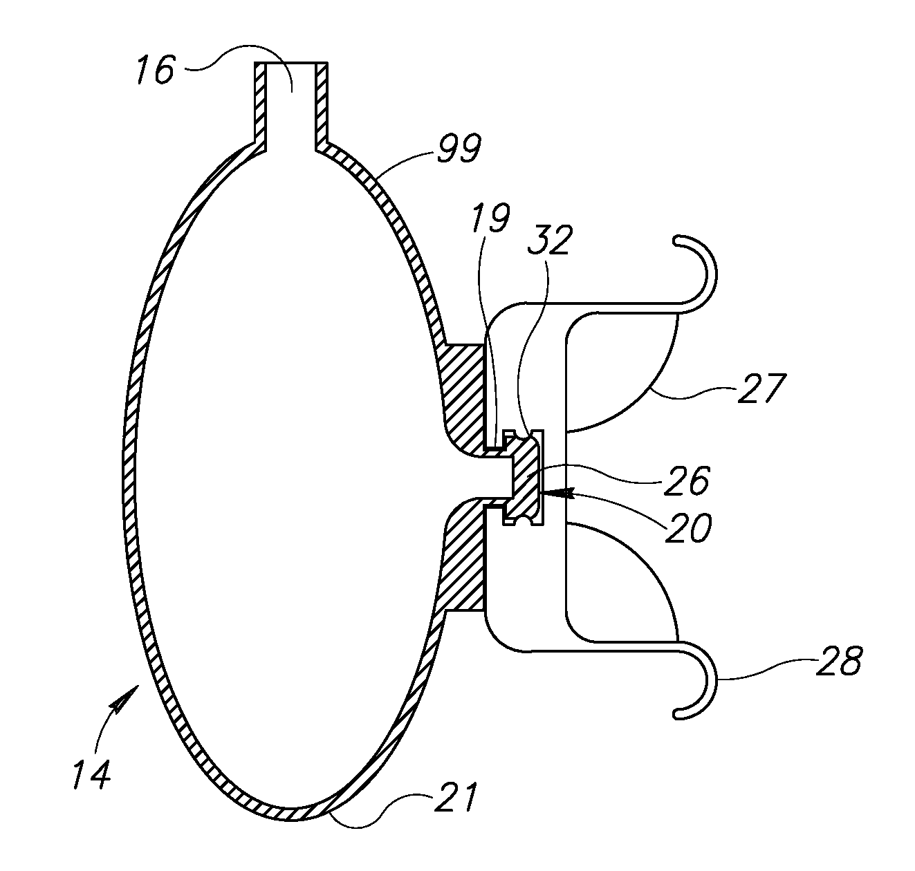
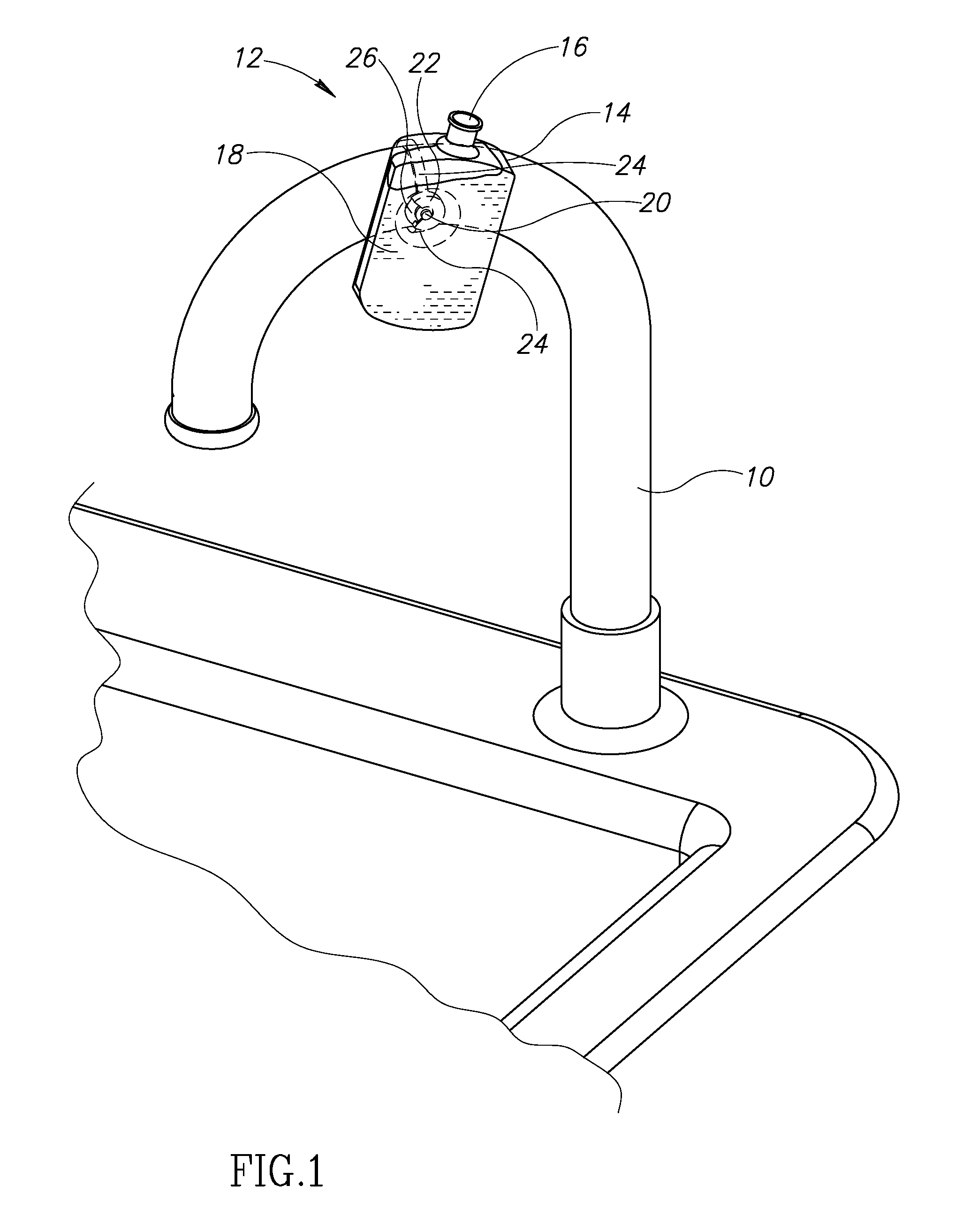
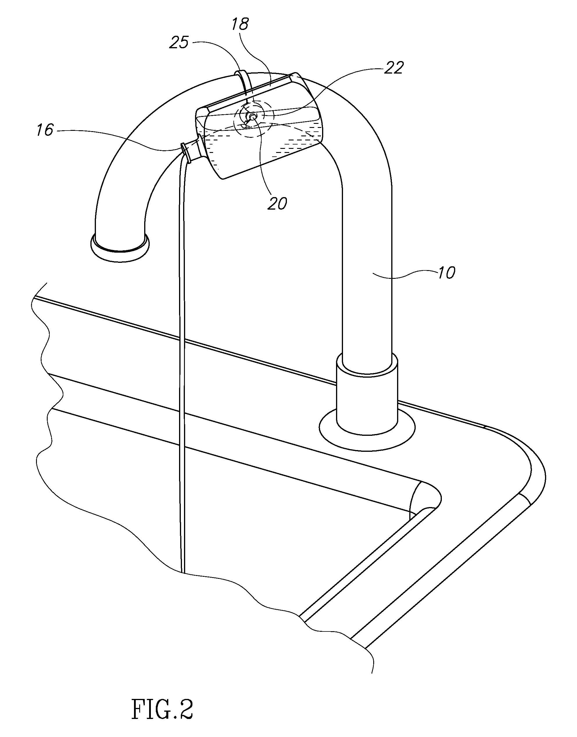
[0104]The present invention comprises a novel apparatus for fluid dispensers targeted at consumers or end users, and a novel system and method of merchandising that is enabled by the novel apparatus. The apparatus comprises mechanisms and methods for allowing a consumer to suspend one or more fluid dispensers in a strategic location in the vicinity of where the fluid will actually be used. The suspension mechanism is simple to manufacture and use yet highly adaptable to accommodate the range of potential fixtures from which consumers may wish to suspend the dispensers. Furthermore, the exemplary embodiments comprise an apparatus for adapting a fluid reservoir or container, often provided in advance with an outlet, to be attached to a fixture via a coupler. The structural relationship between either the coupler and fixture, or the coupler and coupled fluid container, is such that a user can manually, controllably and incrementally rotate the fluid container such that its outlet trave...


PUM


Abstract

A novel and useful mountable and rotatable fluid dispenser comprises a container or fluid reservoir and a coupler. The container is adapted to be suspended from, and rotationally coupled to, a mounting point selected by a consumer. The container has at least one outlet at a first position on an outer surface thereof. The coupler is located at a second position on the outer surface and attachable by a consumer to the selected mounting point. The coupler is adapted to be re-attachable as desired by the consumer. The fluid dispenser further comprises a position stabilization mechanism for maintaining the user-determined position of the container when not being acted upon, whereby a consumer controls the dispensing of fluid from the container by re-orienting the height of the outlet between any non-dispensing position and any dispensing position without decoupling the container from the mounting point.

Description

REFERENCE TO PRIORITY APPLICATION[0001]The present application claims priority from U.S. Provisional Application Ser. No. 60 / 670,459, filed Apr. 11, 2005, entitled “Kitchen and Bath Dispenser System and Apparatus”.FIELD OF THE INVENTION[0002]The present invention relates generally to a system and apparatus for dispensing flowable products. More particularly, the present invention relates to consumer-suspended, fluid product dispensing containers for dispensing consumer quantities of fluids ranging from liquid to granular solid powder.BACKGROUND OF THE INVENTION[0003]Many consumer products such as dishwashing detergent, hand soap, shampoo, hair conditioner, toothpaste, condiments including mustard, ketchup, mayonnaise, syrup, honey and viscous food fluids such as jams, jellies, peanut butter, and the like, are packaged in containers that are often recloseable and have a capacity anywhere from an individual portion to 64 fluid ounces or more. The containers are typically made from mol...

Claims


Application Information

Patent Timeline
Patent Type & Authority Patents(United States)
IPC IPC(8): B67D3/00A47K5/12A47K5/13B67D7/84
CPCA47K5/12A47K5/13A47K2005/1218
Inventor LICARI, YAFFA SHEINA
Owner HURWITZ SARAH DEBORAH DR
Learn More