Vehicle peripheral obstacle notification system

a technology for identifying obstacles and vehicles, applied in the field of vehicle peripheral obstacle identification systems, can solve problems such as poor visibility, inability to acquire images, and possible problems, and achieve the effect of improving the efficiency of the entire work being don

Active Publication Date: 2016-10-11
NIHON KENKI CO LTD
View PDF19 Cites 12 Cited by
  • Summary
  • Abstract
  • Description
  • Claims
  • Application Information

AI Technical Summary

Benefits of technology

[0014]According to the present invention, without recourse to an onboard under-vehicle camera, it is possible to detect and image a moving obstacle at a position not appearing in a composite bird's-eye view merged with a view immediately under the vehicle body and covering the surroundings of the host vehicle, the position and image of the moving obstacle being superimposed onto a display screen prompting the user to know quickly what kind of obstacle is detected at what location. This allows the user easily to determine how to deal with the detected moving obstacle. As a result, the efficiency of the entire work being done is improved.

Problems solved by technology

For this reason, if the above-mentioned known technique is applied to the construction machines, troubles may well be expected such as the inability to acquire images with poor visibility due to mud, oil, or dirt sticking to the lens of the onboard under-vehicle camera, or the destruction of the camera proper caused by scattering gravel or rock.
If the onboard under-vehicle camera suffers from such poor visibility or is destroyed outright, it is impossible to detect or identify obstacles in the space under the vehicle body, with nothing appearing in the image being displayed.
This can be a significant impediment to securing safety during work.

Method used


Image

  • Vehicle peripheral obstacle notification system
  • Vehicle peripheral obstacle notification system
  • Vehicle peripheral obstacle notification system

Examples


first embodiment

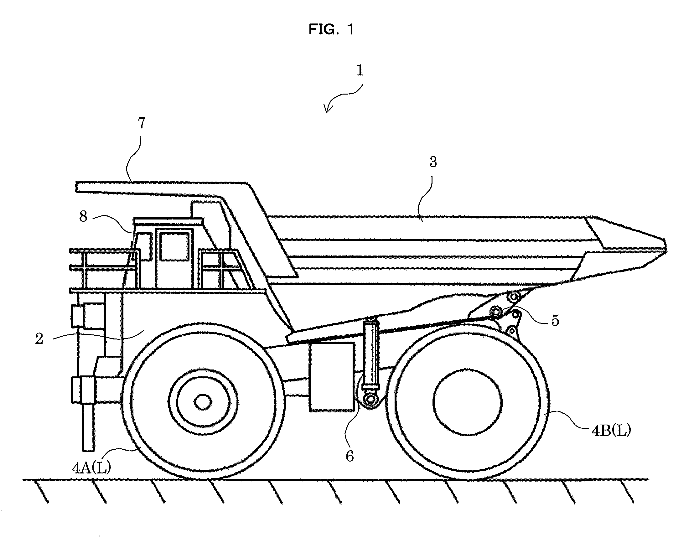
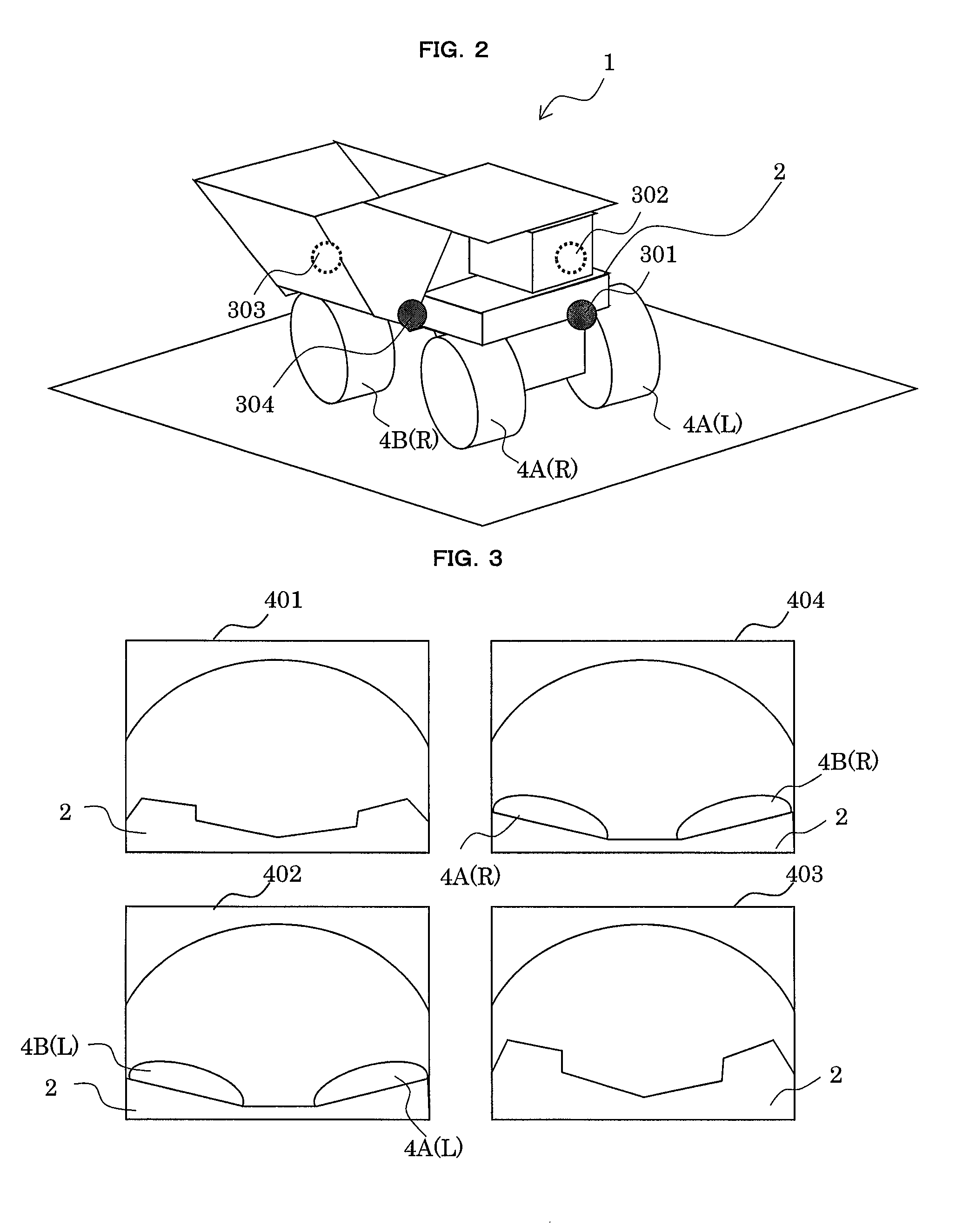
[0034]FIG. 1 is a side view showing a dump truck having a vehicle peripheral obstacle notification system as the first embodiment of the present invention. A dump truck 1 (host vehicle) 1 shown in FIG. 1 is furnished primarily with a vehicle body 2 made of a sturdy frame structure, a vessel (bed) 3 mounted tiltably on the vehicle body 2, and a left front wheel 4A(L) and a left rear wheel 4B(L) attached to the vehicle body 2.

[0035]An engine (not shown) for driving the rear wheels 4B is mounted on the vehicle body 2. Typically, the engine has an engine control unit (ECU), and the revolutions of the engine are controlled by command signals from the ECU regulating the flow rate of the fuel being supplied to the engine.

[0036]The vessel 3 is provided to carry cargoes such as rubble and coupled tiltably to the vehicle body 2 via a pin coupling part 5, among others. Under the vessel 3 are two tilting cylinders 6 arranged in the direction of the vehicle width with a predetermined distance th...

second embodiment

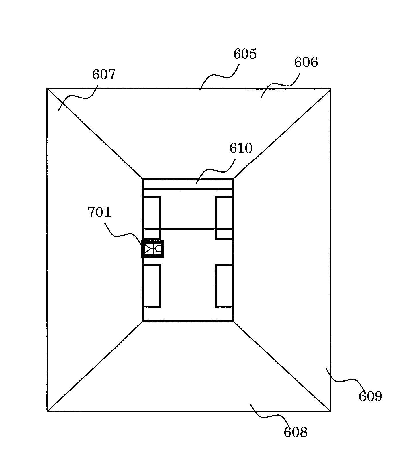
[0071]A vehicle peripheral obstacle notification system as the second embodiment of the present invention is explained below with reference to the accompanying drawings. FIG. 10 is a flowchart showing the processing steps for highlight display performed by the vehicle peripheral obstacle notification system as the second embodiment. FIG. 11 is a conceptual view explaining how an obstacle outside the image areas is typically detected by the vehicle peripheral obstacle notification system as the second embodiment. In FIGS. 10 and 11, the same reference numerals denote the same or corresponding components in FIGS. 1 through 9, so that their detailed explanations will be omitted hereunder.

[0072]The structure and the manner of operation of the vehicle peripheral obstacle notification system as the second embodiment are substantially the same as those of the first embodiment. The second embodiment differs from the first embodiment as follows: if a moving object is detected which is under ...

third embodiment

[0081]A vehicle peripheral obstacle notification system as the third embodiment of the present invention is explained below with reference to the accompanying drawings. FIG. 12 is a conceptual view explaining how an obstacle outside the image areas is typically detected by the vehicle peripheral obstacle notification system as the third embodiment. In FIG. 12, the same reference numerals denote the same or corresponding components in FIGS. 1 through 11, so that their detailed explanations will be omitted hereunder.

[0082]The structure and the manner of operation of the vehicle peripheral obstacle notification system as the third embodiment are substantially the same as those of the first embodiment. The third embodiment differs from the first embodiment as follows: if a moving object is detected which is under the host vehicle 1 and which does not appear in the composite image 605, the detected position is highlighted, and the image of the detection result (i.e., image of the obstacl...


PUM


Abstract

A vehicle peripheral obstacle notification system, used on a construction machine, detects a moving obstacle, gives composite display of the detected moving obstacle, and notifies a user thereof, the moving obstacle being at a location not appearing in a composite bird's-eye view obtained by onboard cameras acquiring images of the surroundings of the vehicle including an image immediately under the vehicle body. The system has a composite image formation part that extracts composite image formation areas from the surrounding images to compose a composite bird's-eye image. A moving obstacle is detected using the surrounding images and it is decided whether the detected position of the moving obstacle is inside or outside the composite image formation areas. If the detected position is determined to be outside the composite image formation areas, information about the detected position is extracted and an image thereof is output for superimposition onto the composite bird's-eye image.

Description

BACKGROUND OF THE INVENTION[0001]1. Field of the Invention[0002]The present invention relates to a vehicle peripheral obstacle notification system. More particularly, the invention relates to a vehicle peripheral obstacle notification system which, used on a construction machine such as a large-sized dump truck working at a mine, performs detection and notification of obstacles near the vehicle body so as to efficiently evade the contact with such nearby obstruction.[0003]2. Description of the Related Art[0004]There exists an under-vehicle image display control device that generates a bird's-eye image covering the surroundings of the vehicle, and displays an under-vehicle image together with an image of the vehicle itself in a transparent manner. In addition to onboard cameras such as a rearview camera for imaging the vehicle surroundings, there is provided an onboard under-vehicle camera positioned at the bottom of the vehicle rear to acquire an image immediately under the bottom o...

Claims


Application Information

Patent Timeline
Patent Type & Authority Patents(United States)
IPC IPC(8): G06K9/00B60Q9/00B60R1/00G06T11/60G06T7/20E02F9/26
CPCB60Q9/008B60R1/00G06K9/00791G06K9/00805G06T7/2033G06T11/60B60R2300/8093E02F9/261G06T2207/10016G06T2207/20221G06T2207/30261G06T7/246G06V20/56G06V20/58
Inventor FUKUDA, YOSHIBUMIONUMA, CHIEKOISHIMOTO, HIDEFUMIOOTA, MORITAKAKAWAMATA, YUKIHIRO
Owner NIHON KENKI CO LTD
Why Eureka
Try Eureka