Paddle card assembly for high speed applications

a high-speed application and cable technology, applied in the direction of electrical equipment, connection, coupling device connection, etc., can solve the problem of negative influence on the discontinuity of the impedance profile of the cable assembly, and achieve the effect of reducing crosstalk, cost saving, and reducing crosstalk

Active Publication Date: 2016-10-11
MOLEX INC
View PDF65 Cites 17 Cited by
  • Summary
  • Abstract
  • Description
  • Claims
  • Application Information

AI Technical Summary

Benefits of technology

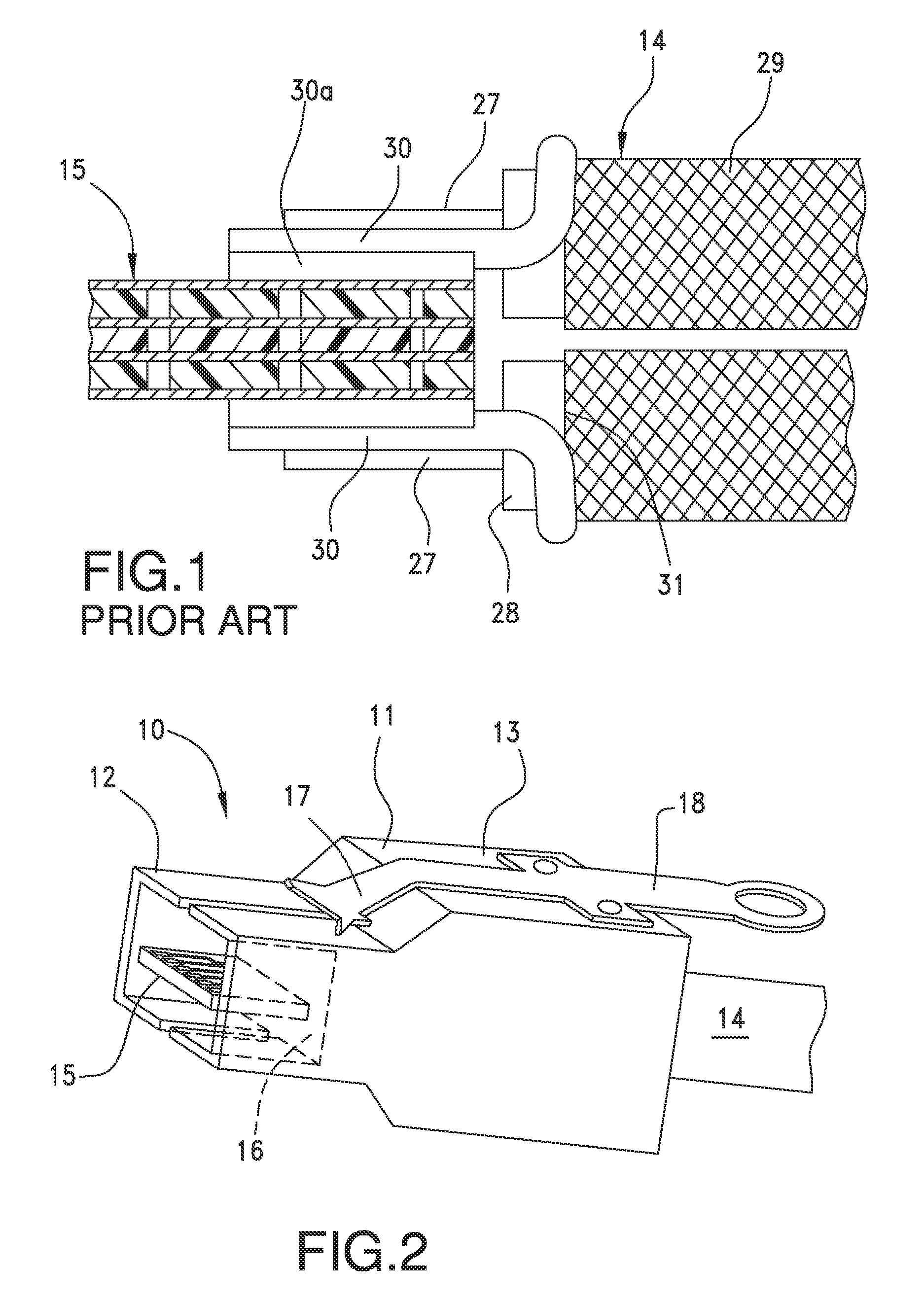
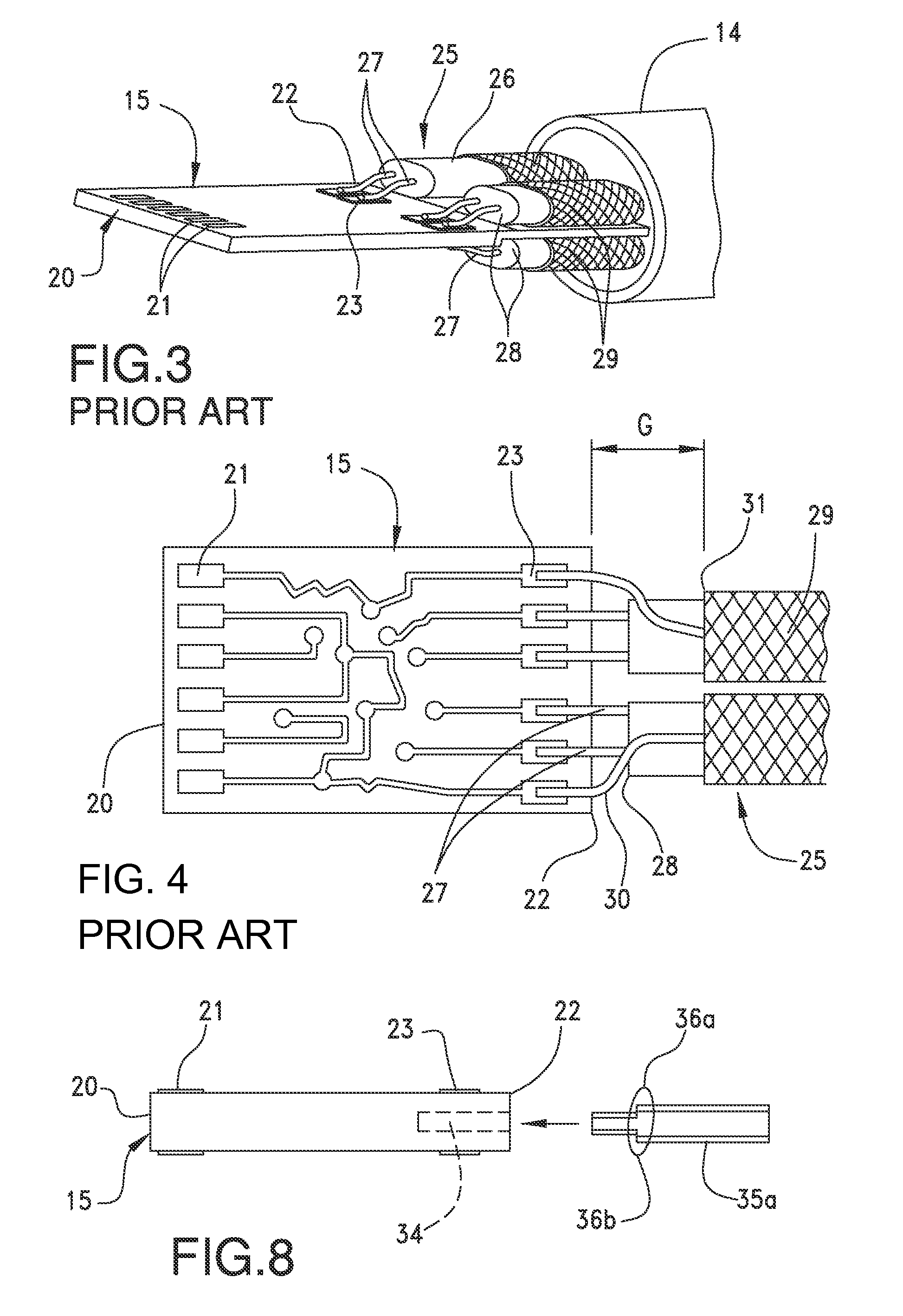
[0008]The extension portion of the circuit board extends rearwardly into this gap between the leading edge of the shield and the trailing edge of the circuit board. It fills the intervening space between top and bottom pairs of cable wires, and because the extension portion supports at least one ground plane layer, it provides shielding between aligned pairs in the vertical direction of the cable assembly. This shielding reduces crosstalk in the termination area, without the need for additional, separate shielding components. The extension portion has a thickness that is less than the thickness of the circuit board base portion so that the circuit board has a stepped configuration when it is viewed from the side. The thickness of this extension portion may be chosen to provide a spacing template for the cable wires as it will preferably fit snugly in the horizontal gap that exists in the vertical direction between wires on opposite surfaces of the circuit board. The reduction in crosstalk between the vertically aligned wires without utilizing additional components, offers a cost saving in manufacturing of cable assemblies of the Present Disclosure. Moreover, the stepped profile of the circuit board provides for an intervening element that can assist in providing strain relief to the cable assembly when the circuit board is overmolded with an insulative material at least in the termination area. Suitable overmolding materials include plastics and / or epoxies.
[0009]In another embodiment, the extension portion has the same thickness as the remaining portion of the circuit board, and is configured to receive the cable wires by way of one or more cavities, or channels, formed in the extension portions. The cavity is preferably formed in the circuit board insulative layer to a depth such that the conductors extend out of the cable wires at the surface of the circuit board, so there is no relatively large spacing therebetween that could affect the connection between the wires and the circuit board. In other words, the wire conductors extend out of the wires at an elevation where the bottom surfaces of the conductors will match the upper surface of the termination areas on the circuit board. In this manner, virtually no stress is created at the conductor-circuit board junction and the conductor and wire will not induce any stress on these junctions.
[0010]In this embodiment, one cavity may be formed in the circuit board extension portion which accommodates a wire pair. In yet another embodiment, a pair of cavities may be formed in the surfaces of the circuit board extension portions to accommodate each wire pair. In some connectors constructed in accordance with the present disclosure the cable may have two wire pairs and, as such, the circuit board extension portion can accommodate two pairs of cavities while in other connectors, there may be four-to-six differential signal pairs and thus single cavities will need to accommodate each differential wire pair. The cavities may extend down to the inner ground plane or they may include a thin layer of board material over them to prevent accidental shorting.

Problems solved by technology

This area is prone to increasing crosstalk and negatively influencing discontinuities in the impedance profile of the cable assembly.

Method used


Image

  • Paddle card assembly for high speed applications
  • Paddle card assembly for high speed applications
  • Paddle card assembly for high speed applications

Examples


Embodiment Construction

[0026]While the Present Disclosure may be susceptible to embodiment in different forms, there is shown in the Figures, and will be described herein in detail, specific embodiments, with the understanding that the Present Disclosure is to be considered an exemplification of the principles of the Present Disclosure, and is not intended to limit the Present Disclosure to that as illustrated.

[0027]As such, references to a feature or aspect are intended to describe a feature or aspect of an example of the Present Disclosure, not to imply that every embodiment thereof must have the described feature or aspect. Furthermore, it should be noted that the description illustrates a number of features. While certain features have been combined together to illustrate potential system designs, those features may also be used in other combinations not expressly disclosed. Thus, the depicted combinations are not intended to be limiting, unless otherwise noted.

[0028]In the embodiments illustrated in ...


PUM


Abstract

A paddle card assembly is disclosed for use in providing a high speed transmission line for connecting electronic devices together. The paddle card takes the form of a circuit board that has two distinct portions, a base portion to which wires of a cable are terminated, and an extension portion that extends rearwardly toward the cable wire in order to extend between sets of wires. The extension portion has one or more ground plane layers formed therewith and supported thereby and as such, the extension portion places a ground plane in the termination area of the connector, rear of the trailing edge of the paddle card to provide shielding between pairs of wires on opposite sides of the paddle card where the cable shields are cut back. The extension portion may have either a reduced thickness, or wire-receiving channels formed therein which accommodate portions of the wires of the cable.

Description

REFERENCE TO RELATED APPLICATIONS[0001]The Present Disclosure is a Continuation-in-Part Application of prior-filed U.S. patent application Ser. No. 13 / 745,329, entitled “Paddle Card Assembly for High Speed Applications,” filed on 18 Jan. 2013 with the United States Patent and Trademark Office. The content of the aforementioned Patent Application is incorporated in its entirety herein.BACKGROUND OF THE PRESENT DISCLOSURE[0002]The Present Disclosure relates generally to cable interconnection systems, and, more particularly, to improved cable assemblies for use in high speed data transmission applications.[0003]Conventional cable interconnection systems are found in electronic devices such as routers, servers and the like, and are used to form signal transmission lines. These transmission lines may extend between chip members and connectors, connectors in two different devices, and between devices themselves. Often, differential signal wires are used for each such transmission line in ...

Claims


Application Information

Patent Timeline
Patent Type & Authority Patents(United States)
IPC IPC(8): H01R12/53H01R13/6592H01R12/72H01R9/03
CPCH01R13/6592H01R9/032H01R12/53H01R12/721H01R13/65912
Inventor ROST, MICHAELBUGG, MARK ALANSCHULZ, DARIAN ROSS
Owner MOLEX INC
Why Eureka
Try Eureka