Pneumatic load-transfer system and method for mating an integrated deck with a pre-installed platform substructure

a technology of platform substructure and load transfer system, which is applied in the direction of artificial islands, foundation engineering, construction, etc., can solve the problems of potential damage, relative motion between the vessel and the deck may pose a potential danger of damage, and damage to the structure, and achieves the effect of easy adjustment of vertical support stiffness, low cost and high reliability

Inactive Publication Date: 2016-10-18
CHINA NAT OFFSHORE OIL CORP +1
View PDF2 Cites 0 Cited by
  • Summary
  • Abstract
  • Description
  • Claims
  • Application Information

AI Technical Summary

Benefits of technology

[0020]The pneumatic load-transfer system disclosed herein is a passive system capable of performing a floatover installation in both swell conditions and calm water environments with high reliability. The disclosed system is less expensive comparing with existing floatover methods. The major improvement of the present disclosure is to provide a pneumatic system at separating surfaces to perform multiple functions such as deck heave motion reduction, air gap enhancement, shock absorbing and the ability to adjust vertical support stiffness easily.
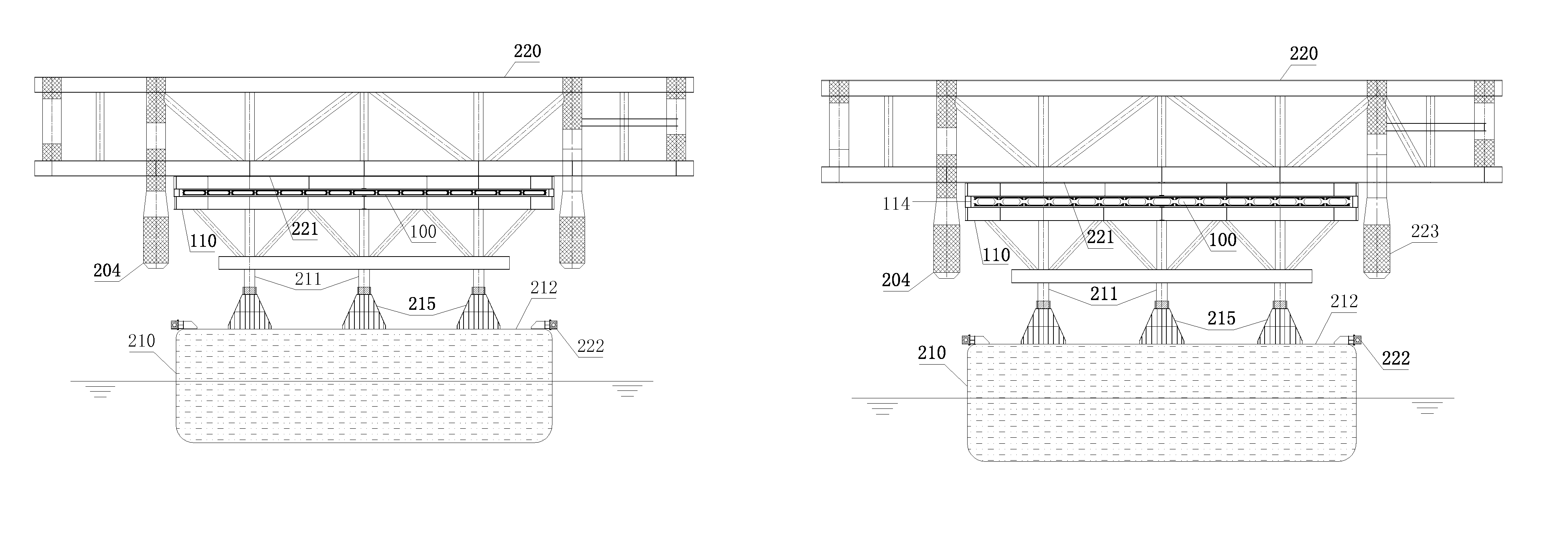
[0021]In accordance with one aspect of the present disclosure, the system provides a layer of air pads composed of a plurality of SLABs between the tops of supports at a vessel deck and the bottom surfaces of a platform deck. When air is injected to all SLABs at the same time and with the same pressure, these SLABs can be expanded to lift the deck upwardly generating an air gap quickly between the supports and the deck. The layer then becomes a spring in a series arrangement with the water plane spring acting at the floatover vessel. Once the air gap is stabilized, the deck will achieve a stable heave motion by its own and telescopic sleeves are installed between the upper covers of these SLABs and the bottom covers of these SLABs to ensure the stability of the deck against wind induced forces, during its own heave motions. Two favorable consequences are resulted to the deck heave motions: 1) a relative heave motion is created between the deck and the vessel to cause the reduction of relative heave motions between the deck and the re-installed substructure at mating surfaces; 2) the dynamic inertial force, generated by the relative heave motions between the deck and the vessel, can be utilized to reduce the vessel heave motion with a proper adjustment of the stiffness of this layer of air pads.
[0022]In accordance with another aspect of the present disclosure, the stiffness adjustability of the layer of SLAB air pads can be utilized to suit different environmental conditions at an installation site. Based on the site existing environmental conditions (Hs and Tp), the stiffness of the layer can be adjusted to achieve a minimum heave motion of the deck under the site waves, relative to the installed substructure and prior to the entering of the substructure slot. In this manner, expensive LMUs in a traditional High-Deck method could be replaced with inexpensive sand cans and most floatover installation related apparatuses can be reused for other floatover applications to further reduce the total floatover installation system costs.
[0023]In accordance with a further aspect of the present disclosure, the system is a simple and passive system without the employment of powerful hydraulic systems and other mechanical devices. The load transfer process, both in mating and separating phases, is conducted through the combination of a simple ballasting operation and a simple set of air releasing / injecting operations. Therefore, the reliability of the whole system is improved significantly, especially for the separating operation where any steel-to-steel contact is NOT allowed. With the improvement of the system reliability, the safety of the associated floatover installation is also improved.

Problems solved by technology

Impacts will occur between the deck downwardly extending legs and substructure upwardly extending legs and such repeated impacts may result in damages to both structures.
Once the majority of the deck load has been transferred to the substructure upwardly extending legs, due to the vessel ballasting induced vessel draft change, the deck starts to separate from the supports at the barge deck Immediately after the initial separation, the relative motions between the vessel and the deck may pose a potential danger of damages due to the impact between the two bodies induced by vessel motions.
The potential damage during the mating phase usually occurs at the contact surfaces (mating surfaces) between the downwardly extending deck legs and the substructure upwardly extending legs.
The potential damage during the separating phase usually occurs at the contact surfaces (separating surfaces) between the support tops at the vessel deck and the associated deck bottom structure.
In any floatover installation methods and systems, the governing issue is how to overcome the barge heave motions during the mating phase and during the separating phase.
In addition, this method is relatively inexpensive comparing with other existing floatover methods for a floatover installation under a similar environment.b. Disadvantages: There are two major disadvantages for this method: 1) this method and system are only suitable for relative calm waters with the maximum vessel heave motions less than 0.5 m (about 1.5 ft); 2) these expensive LMUs are designed for one time use only.2. Uni-Deck method is designed to conduct a floatover installation under swell conditions.
Under such high heave motions, conventional High-deck method could not be employed because LMUs and DSUs have to be stacked very high and the barge draft variations have to become very large in order to accommodate such high heave motions during the mating and separating operations.
Steel-to-steel contact is not allowed at any separating surfaces, in order to avoid any potential damages both to the deck structure and to these supports at vessel deck.a. Advantages: this system is capable to perform a floatover installation under swell conditions.b. Disadvantages: the key disadvantage of this system is that the system is an active system employing expensive hydraulic jacks and a complicated control system.
If the jack lowering operation could not be executed properly and sufficient enough, such as one jack could not be lowered along with other jacks together, steel-to-steel impact could happen with damages to both the deck and to the supports.
Another disadvantage is that the system is an expensive one including the costs of utilizing these jacks and the associated controlling system during the installation, the pre-installation testing and the removal of these jacks, plus the expensive maintenance costs.

Method used


Image

  • Pneumatic load-transfer system and method for mating an integrated deck with a pre-installed platform substructure
  • Pneumatic load-transfer system and method for mating an integrated deck with a pre-installed platform substructure
  • Pneumatic load-transfer system and method for mating an integrated deck with a pre-installed platform substructure

Examples


Embodiment Construction

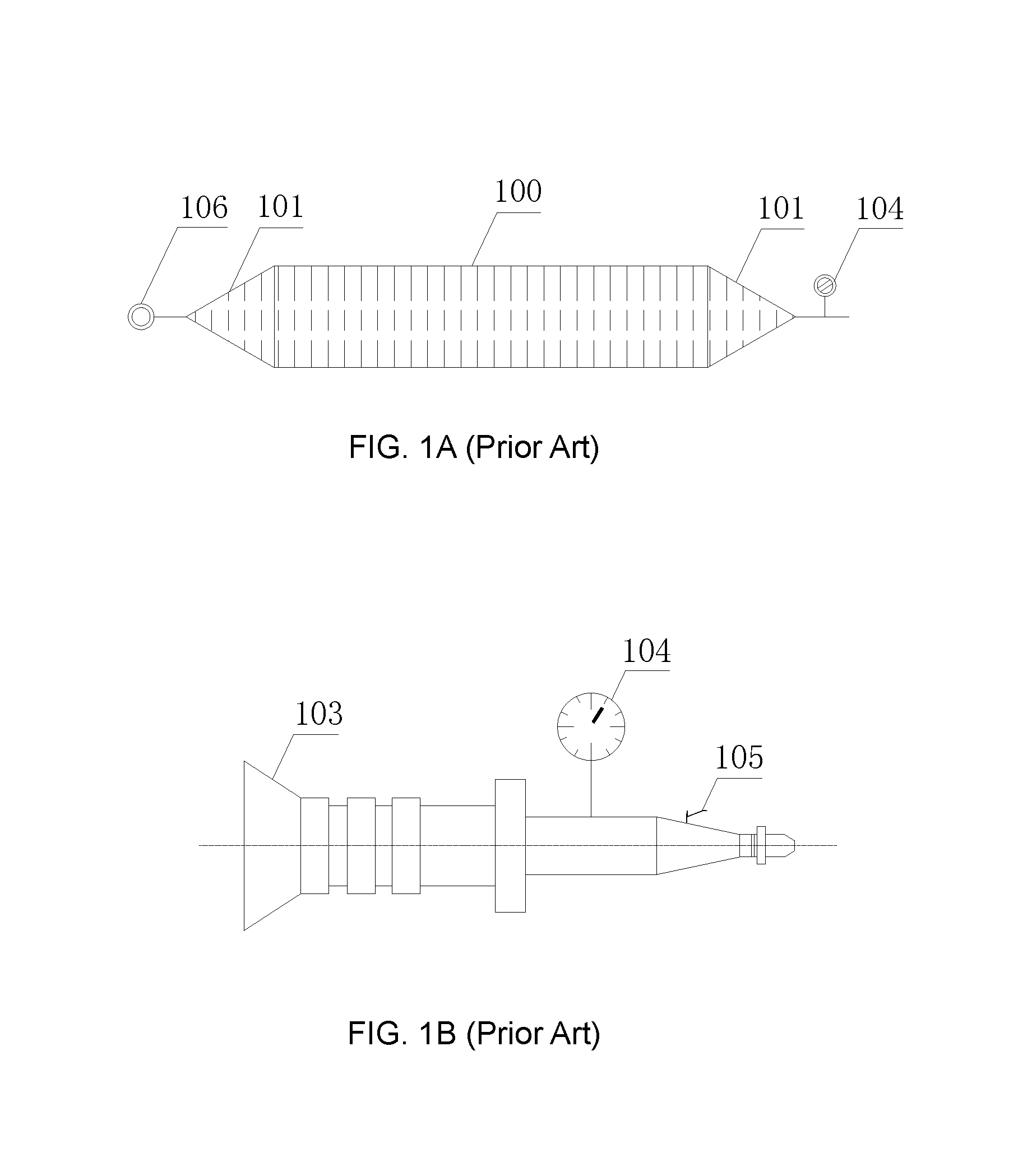
[0045]Shipbuilding in sand beaches started in 1980's in Southern China. Builders place wood blocks on sand beach and start ship construction on the tops of these blocks with the utilization of land cranes. When the construction is complete, a special type of air bags, Ship Launching Air Bags (SLAB), is placed under the ship keel longitudinally between two rows of wood blocks. Injecting air to these SLABs and the whole ship can be lifted off these wood blocks. After the lifting operation, these wood blocks can be then removed off the ship keel. Once cutting holding lines, the ship will be moved toward the sea along with the rolling of these SLABs.

[0046]The ship launching method described above has been successfully used in China for over 20 years. Recently, the applications of SLAB have expanded to other areas, such as ship salvages and a floatation tool for the transportation of a large concrete structure for a bridge. Over the years, SLABs have become a mature, reliable and off she...


PUM


Abstract

A new pneumatic load transfer and shock absorbing system is disclosed. The pneumatic system includes a layer of air-bags to perform two basic functions during a floatover installation operation: 1) lifting the platform deck from the support to create additional air gaps at the mating surfaces, and the heave motions of the lifted platform deck may be reduced; 2) performing as a shock absorbing device with variable vertical stiffness easily controlled by the air-bag internal air pressure during the mating operation and the separation operation.

Description

FIELD OF THE INVENTION[0001]The disclosure relates generally to a system for transferring an integrated offshore platform deck load from a vessel to a pre-installed platform substructure under rough seas or under swell conditions.BACKGROUND OF THE INVENTIONOffshore Floatover Installation[0002]An offshore platform is generally composed of two sections: 1) a substructure such as a jacket for a fixed platform, and 2) a superstructure such as a deck to be installed on the top of a substructure.[0003]A floatover installation is referred to a set of offshore operational procedures to install an integrated platform deck onto a pre-installed substructure at an offshore location under open sea environments.[0004]The first procedure is the transportation of a platform deck from an onshore fabrication yard to an offshore installation site. When a barge or a heavy transport vessel loaded with the integrated deck arrives at the offshore installation, the substructure should be already installed ...

Claims


Application Information

Patent Timeline
Patent Type & Authority Patents(United States)
IPC IPC(8): E02B17/08E02B17/02E02B17/00
CPCE02B17/024E02B17/021E02B17/08E02B2017/0043E02B2017/0047
Inventor LEE, JAMESZHONG, WEN JUNYIN, HAN JUNLI, XIN ZHONGFAN, MOZHOU, XIAO HONGCAI, YUAN LANGYANG, XIAO LONGZHANG, XIAO WEIWANG, LIANG
Owner CHINA NAT OFFSHORE OIL CORP
Why Eureka
Try Eureka