Electric motor having segmented stator windings

a stator winding and electric motor technology, applied in the direction of positive displacement liquid engine, piston pump, magnetic circuit shape/form/construction, etc., can solve the problems of process gas heating and additional pressure drop, and achieve the effect of less cogging, less cogging, and more losses in the rotor

Active Publication Date: 2016-10-18
ATLAS COPCO AIRPOWER NV
View PDF158 Cites 7 Cited by
  • Summary
  • Abstract
  • Description
  • Claims
  • Application Information

AI Technical Summary

Benefits of technology

[0039]The stator core is preferably built-up as a series of segments to minimize waste of material and to ease assembly. Neighboring segments can even be equipped with a coil before being fixed to each other.
[0040]The stator core segments are preferably stacked with thin low-loss grain-oriented steel, for this reduces the magnetic losses to a maximum extent at an acceptable cost level.
[0041]The stator core segments are preferably stacked with single piece laminations having outward extensions, for this enhances cooling of the stator core, for this avoids the fixation of separate extensions to the stator core afterwards, and for this increases the leakage inductance of the coils thereby reducing the losses due to current harmonics.
[0042]The shell is preferably constructed by winding a flexible material around the outward extensions with some prestress, for this applies radial force on the outward extensions to automatically retain the stator core, for the resulting polygonally shaped shell prevents any tangential movement of the stator core relative to the shell, for this process is simple and cost-effective, and for this construction avoids the need for a complicated and likely expensive solid shell.
[0043]The motor is of a slotless type, by which the losses due to slot harmonics are virtually eliminated and the losses due to current harmonics and magneto motive force harmonics are drastically reduced.

Problems solved by technology

This causes some heating of the process gas and some additional pressure drop.

Method used


Image

  • Electric motor having segmented stator windings
  • Electric motor having segmented stator windings
  • Electric motor having segmented stator windings

Examples


Embodiment Construction

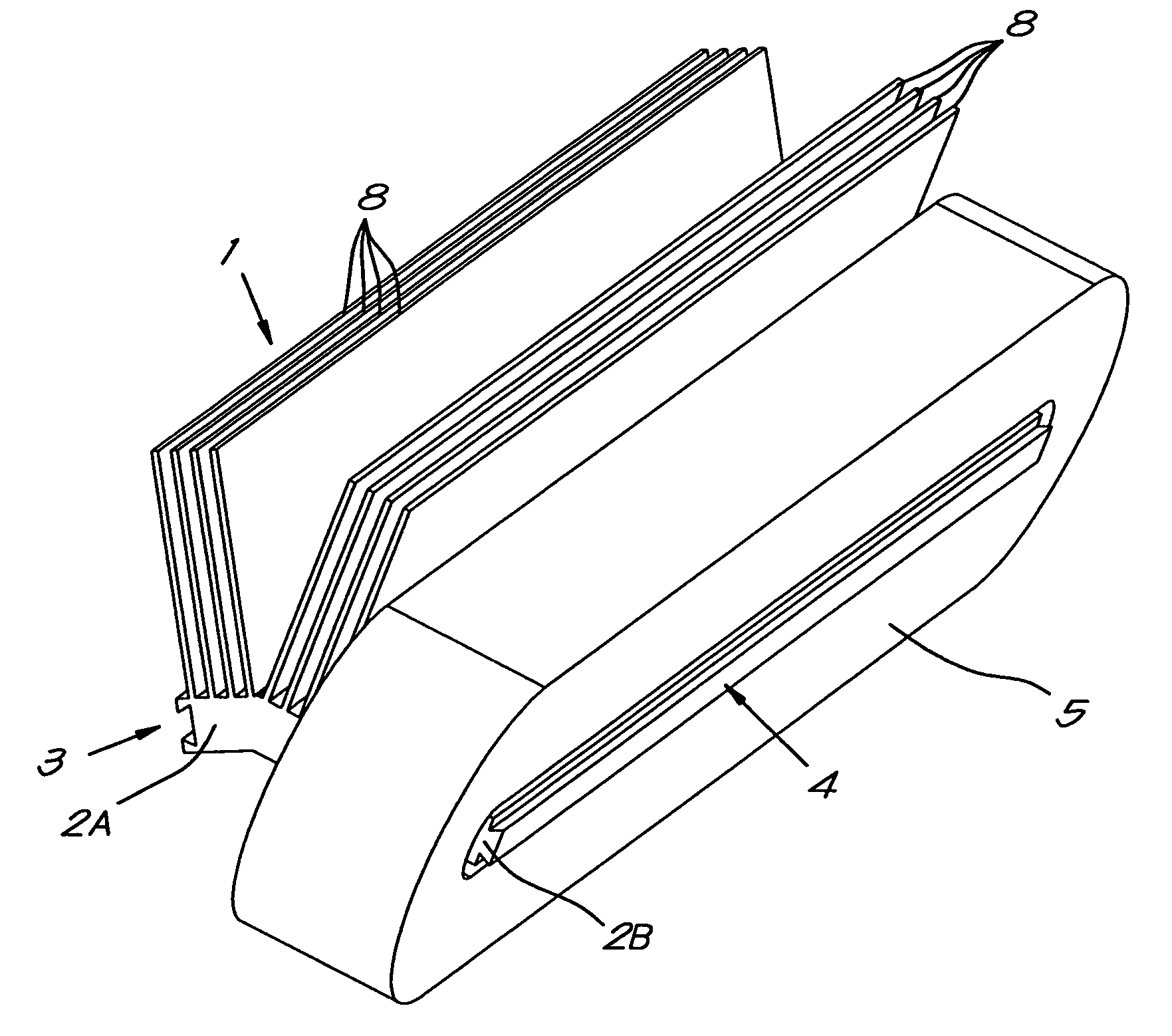
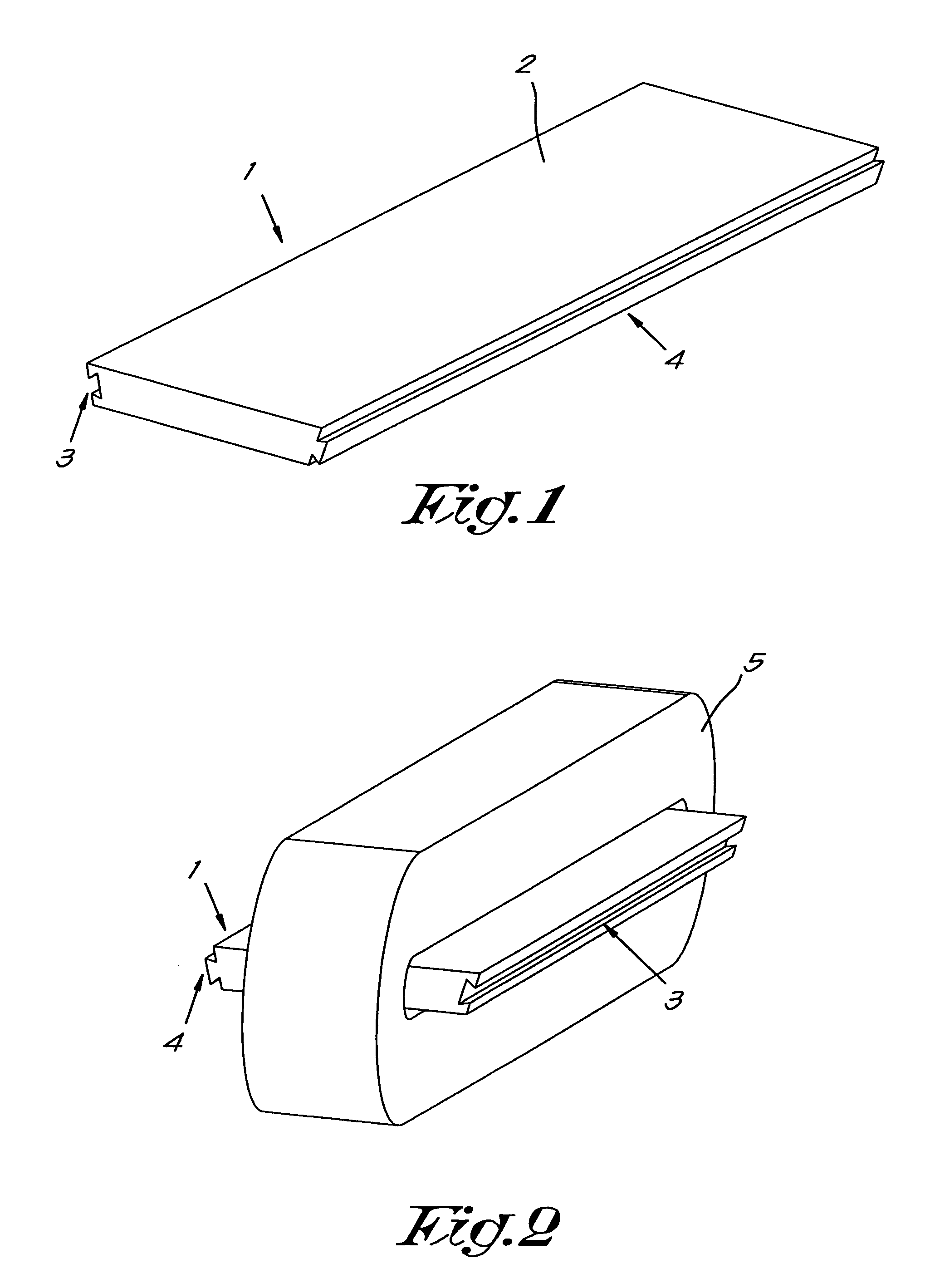
[0066]The stator core of a high speed motor according to the present invention is preferably built-up of a plurality of soft-magnetic core segments 1 comprising a plate shaped segment base 2. The segment base 2 may be straight, as shown in FIG. 1.

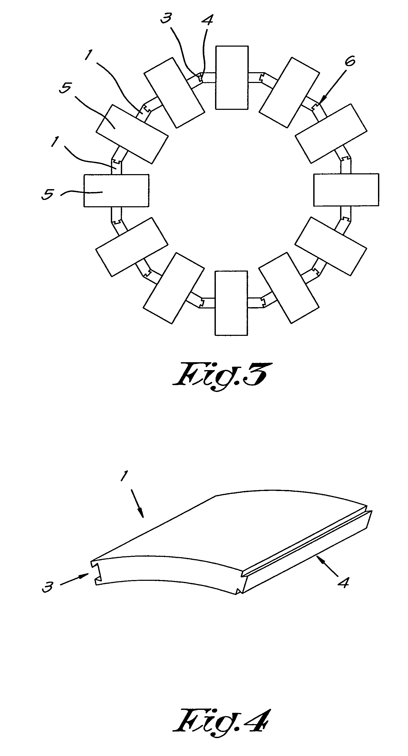
[0067]Preferably, said core segment 1 is further provided with connecting means, in this case in the shape of recesses and protrusions, for interconnecting said core segments 1. According to a preferred characteristic of the invention, the above-mentioned recesses and protrusions are realized in the shape of a dovetail like structure provided along the longitudinal side edges of said segment base 2, more particulary, a dovetail shaped groove 3 on one side edge of the segment base 2 and a dovetail shaped rib 4 on the opposite side edge of said segment base 2.

[0068]Before being connected, a coil 5 is mounted on each individual segment 1, as is illustrated in FIG. 2. There are at least two ways of mounting such a coil 5. In a first process, on...


PUM

PropertyMeasurementUnit
particle sizeaaaaaaaaaa
angleaaaaaaaaaa
angleaaaaaaaaaa

Abstract

A turbocompressor system including a high speed motor (10) including a rotor (12) mounted in a rotative manner relative to the stator, wherein on the rotor (12) one or more impellers (11) are directly fixed, the stator including active motor structures and a shell (7), including a ferromagnetic stator core (6) and a winding being constructed as toroidally wound coils (5), the shell (7) is constructed in such a manner as to create additional open space between the stator core (6) and the shell (7), constituting a cooling channel (15) through which process gas is passed axially for directly cooling the active motor structures and the rotor (12), prior to compression by the one or more impellers (11).

Description

FIELD OF INVENTION[0001]The invention relates to a turbocompressor system comprising a high speed motor and to a method for constructing turbocompressor system.BACKGROUND OF THE INVENTION[0002]In a turbocompressor, one or more impellers are directly connected to a shaft. For their operation, the impellers must be driven at very high rotational speeds, e.g. 20000 rpm up to 100000 rpm and even more. Traditionally, these elevated speeds were attained by combining a standard induction motor and a gearbox, the latter consisting of a large bull gear and at least one small pinion gear. The losses in this gearbox can be considerable, negatively influencing the system efficiency. Moreover, such a gearbox is heavy and it constitutes a major part of the footprint of the entire system.[0003]Meanwhile, advances in high speed motor technology have enabled the development of direct driven turbocompressors. By increasing the motor speed, less torque is required for the same output power. However, s...

Claims


Application Information

Patent Timeline
Patent Type & Authority Patents(United States)
IPC IPC(8): F04D25/06F04D25/08F04D13/06F04D29/58H02K1/20H02K9/06H02K3/00H02K1/14
CPCF04D25/0646F04D13/06F04D25/0606F04D25/082F04D29/584H02K1/148H02K1/20H02K3/00H02K9/06Y10T29/49009F04D29/5806F04D25/06F04D29/28F04D29/58
Inventor VANDE SANDE, HANSPHILIPPI, CORNELIS THEODORUSPAHNER, UWE
Owner ATLAS COPCO AIRPOWER NV
Why Eureka
Try Eureka