Fast settling phase locked loop (PLL) with optimum spur reduction

a phase lock circuit and spur reduction technology, applied in the direction of pulse automatic control, cad, instruments, etc., can solve the problems of control system on the brink of instability, adverse effects on settling time, overshoot in step response, etc., and achieve the effect of sufficient spur reduction and fast settling tim

Active Publication Date: 2016-10-18
DIALOG SEMICONDUCTOR BV
View PDF10 Cites 1 Cited by
  • Summary
  • Abstract
  • Description
  • Claims
  • Application Information

AI Technical Summary

Benefits of technology

[0009]An object to this disclosure is to provide a phase locked loop with sufficient spur reduction and fast settling time.
[0010]Another object of this disclosure is to provide a phase locked loop used within a time division multiplexing radio system such that all time slots within the system are usable eliminating blind-slots within the radio system.

Problems solved by technology

Unfortunately, this brings the control system on the brink of instability and the common remedy is to introduce a zero in the loop transfer function at an appropriate frequency such that the phase margin is sufficient for stable operation.
This zero is also present in the closed loop transfer function, which causes overshoot in the step response.
This has adverse effects on the settling time.
The system choices that were made at its inception have made it very difficult to use all the available time slots and all ten of the available frequencies.
But it is generally too short for the synthesizer in the fixed transmitter / receiver device to tune to a new frequency.
However, if the synthesizer can be tuned in less than 465 μs, one of the active slots is now sacrificed.

Method used


Image

  • Fast settling phase locked loop (PLL) with optimum spur reduction
  • Fast settling phase locked loop (PLL) with optimum spur reduction
  • Fast settling phase locked loop (PLL) with optimum spur reduction

Examples


Embodiment Construction

[0026]In DECT transmitter / receiver devices, the number of transmitter / receiver devices can be increased to the maximum number by eliminating the blind spots that result from the delay that is required for the fixed transmitter / receiver device to tune between frequencies. Increasing the tuning speed of the fixed transmitter / receiver device is accomplished by decreasing the settling time of the transfer function of the phase locked loop.

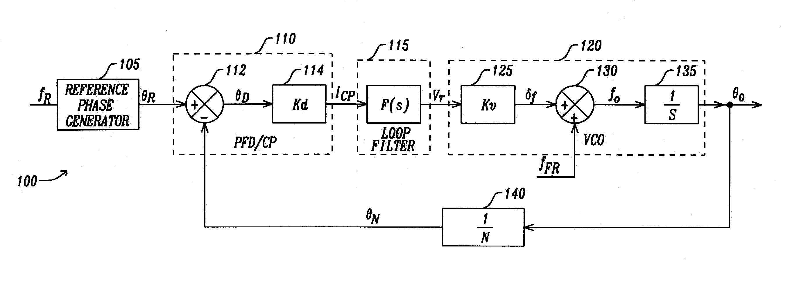
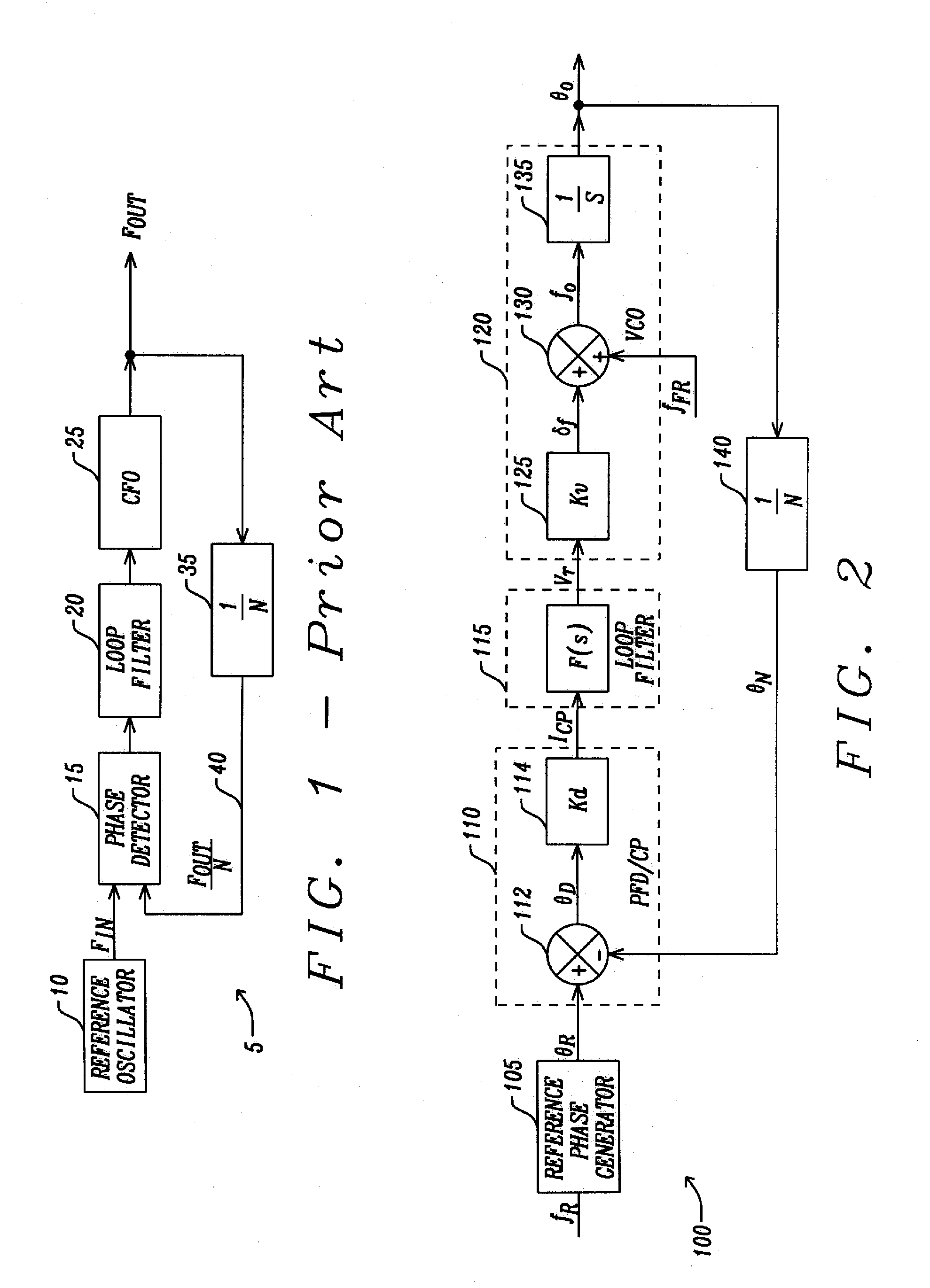
[0027]The phase locked loop is formed of a phase / frequency detector that determines the phase difference between an input reference frequency and submultiple of the output frequency. In some embodiments, the frequency of the input reference signal is approximately equal to the frequency of the generated output signal. The phase difference between the input reference signal and the output signal is the input to a loop filter. The output of the loop filter is the input to an adjustable frequency source such as a voltage controlled oscillator. A copy of t...


PUM


Abstract

A method for constructing a phase locked loop begins with determining spurious frequency component criteria permitted within the PLL. A PLL filter prototype is selected with a desired settling time. A transfer function is generated based on the PLL transfer function that predicts the spurious components. A maximum level of the spurious components produced in the PLL is determined based on the maximum frequency step. If the maximum level of the spurious frequency components produced is too large, the order variable is incremented and the PLL transfer function is determined until the transfer function produces the spurious frequency components that meet the requirements. The components for a loop filter are selected based on the selected PLL transfer function. The adjustable frequency source tuning gain, the phase detector gain, the loop filter gain, and the divide factor are chosen to meet the requirements of the PLL transfer function.

Description

BACKGROUND[0001]1. Field[0002]This disclosure relates generally to design and construction of phase locked loop circuits. More particularly, this disclosure relates to the design and construction of phase locked loop circuits that optimize spurious harmonic frequencies usually caused by non-idealities within the components of the phase locked loop circuits.[0003]2. Description of Related Art[0004]Phase locked loops are used for a variety of clocking and synchronizing purposes as is known to those skilled in the art. In all cases, a compromise must be found between the speed in which phase lock is acquired (settling time) and the spectral purity of the output signal. As an example, a phase locked loop is used for frequency synthesis of a local oscillator signal in a receiver to synchronize the receiver with the incoming signal.[0005]FIG. 1 is a block diagram of phase locked loop of the prior art. Referring to FIG. 1, a phase-locked loop 5 has a stable reference oscillator 10 that pro...

Claims


Application Information

Patent Timeline
Patent Type & Authority Patents(United States)
IPC IPC(8): H03L7/06H03L7/107G06F17/50H03L7/10H03L7/093
CPCH03L7/1075G06F17/5045H03L7/093H03L7/10H03L7/1077G06F2217/02G06F2217/08G06F2217/82G06F2217/84G06F30/30G06F2111/06G06F2111/20G06F2119/10G06F2119/12
Inventor PRUMMEL, JAN
Owner DIALOG SEMICONDUCTOR BV
Why Eureka
Try Eureka