Centrifugal gas separator

a centrifugal gas and separator technology, applied in the direction of separation process, vortex flow apparatus, cleaning equipment, etc., can solve the problems of thien separator and the basic forms of cyclonic separator that can only operate in a vertical orientation, the capacity for horizontal operation, and the added cost of these additional components, so as to reduce the susceptibility of separators, the effect of fast solids settling time and faster settling tim

Active Publication Date: 2020-05-12
ETEROS TECH INC
View PDF37 Cites 0 Cited by
  • Summary
  • Abstract
  • Description
  • Claims
  • Application Information

AI Technical Summary

Benefits of technology

[0011]The present inventors have found that such a separator provides numerous advantages over conventional centrifugal gas separators such as Thien and cyclonic separators.
[0013]The faster settling time also advantageously reduces the susceptibility of the separator to overloading or saturation. Due to their comparatively slower settling times, it is not difficult to overload or saturate a Thien or cyclonic separator, by feeding in solids at a faster rate than they can settle. In contrast, the present inventors have tested an embodiment of the above-described separator in an extreme trial involving solids concentrations unlikely to be encountered in practice, by dumping an entire large bucket of plant-based dust and solids into the separator, and have found that the separator can easily remove the solids without overloading or clogging. The above-described separator therefore tends to be capable of handling significantly higher concentrations of solids than conventional Thien and cyclonic separators.
[0014]The above-described separator also tends to provide other advantages over conventional separators. In comparison to cyclonic separators for example, the above-described separator tends to be considerably smaller, less expensive, less complex, easier to clean and maintain, and more easily tunable to different particle sizes by modifying the sizes of the intake and exhaust ports. In comparison to Thien separators, the above-described separator also tends to be easier to clean and maintain. Embodiments of the above-described separator also typically involve a lower static pressure drop than Thien separators, and a comparable or lower static pressure drop than cyclonic separators, thereby tending to achieve greater energy efficiency and higher volumetric flow rates.

Problems solved by technology

For example, both Thien separators and the basic forms of cyclonic separators can only operate in a vertical orientation, because they require the force of gravity to cause the dust particles to exit from the separator.
Although some manufacturers now offer complex solutions involving numerous additional components and additional airflow injections to allow horizontal operation of cyclonic separators, the added cost, complexity, energy consumption and maintenance demands of these additional components create new disadvantages which offset their capacity for horizontal operation.
Cyclonic separators are also very space-consuming.
This long dwell-time is in itself disadvantageous, and also results in the further disadvantage that it is not difficult to saturate or overload cyclonic and Thien separators by introducing particulate material at a faster rate than it can be removed.

Method used


Image

  • Centrifugal gas separator
  • Centrifugal gas separator
  • Centrifugal gas separator

Examples


second embodiment

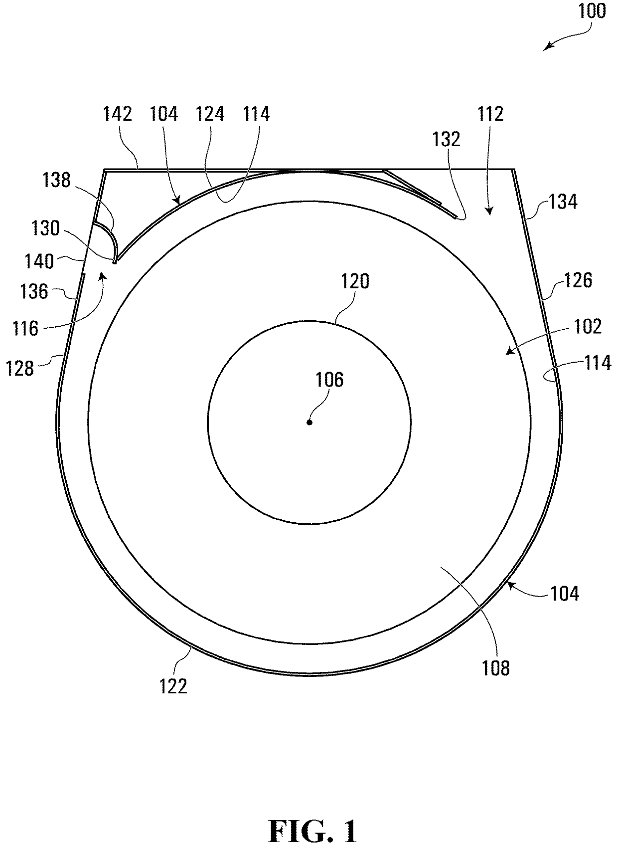
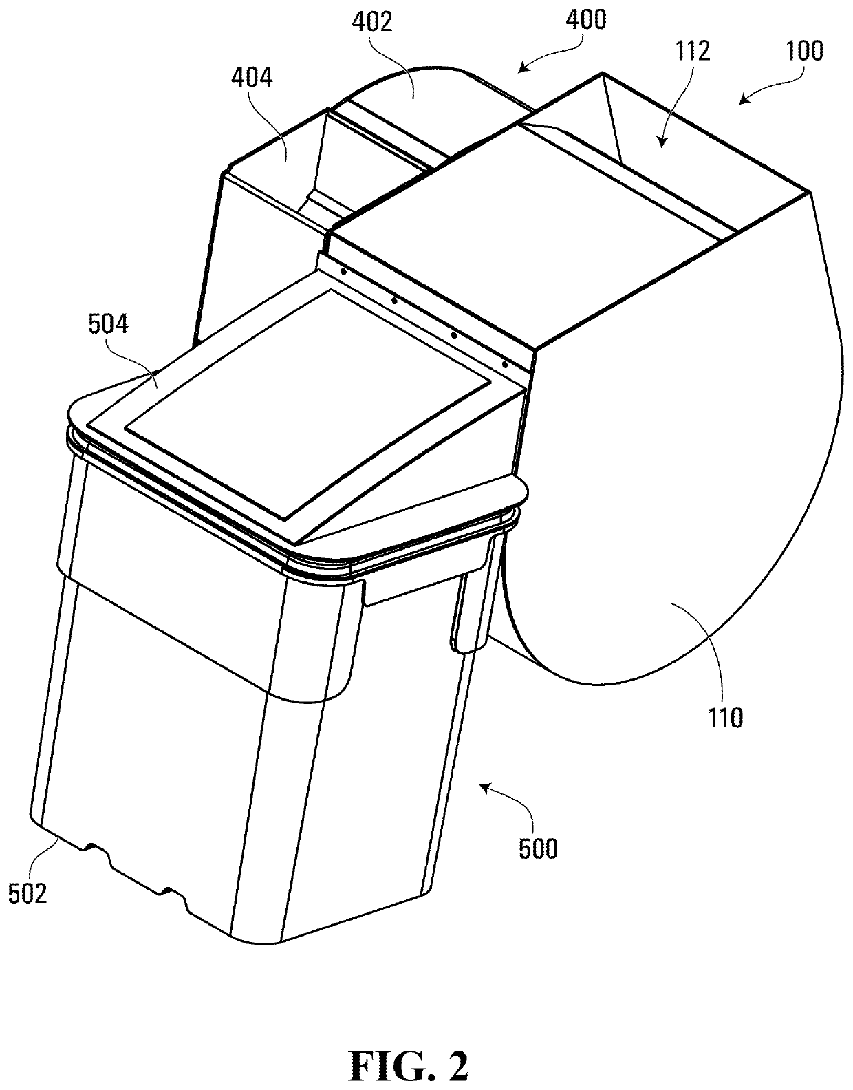
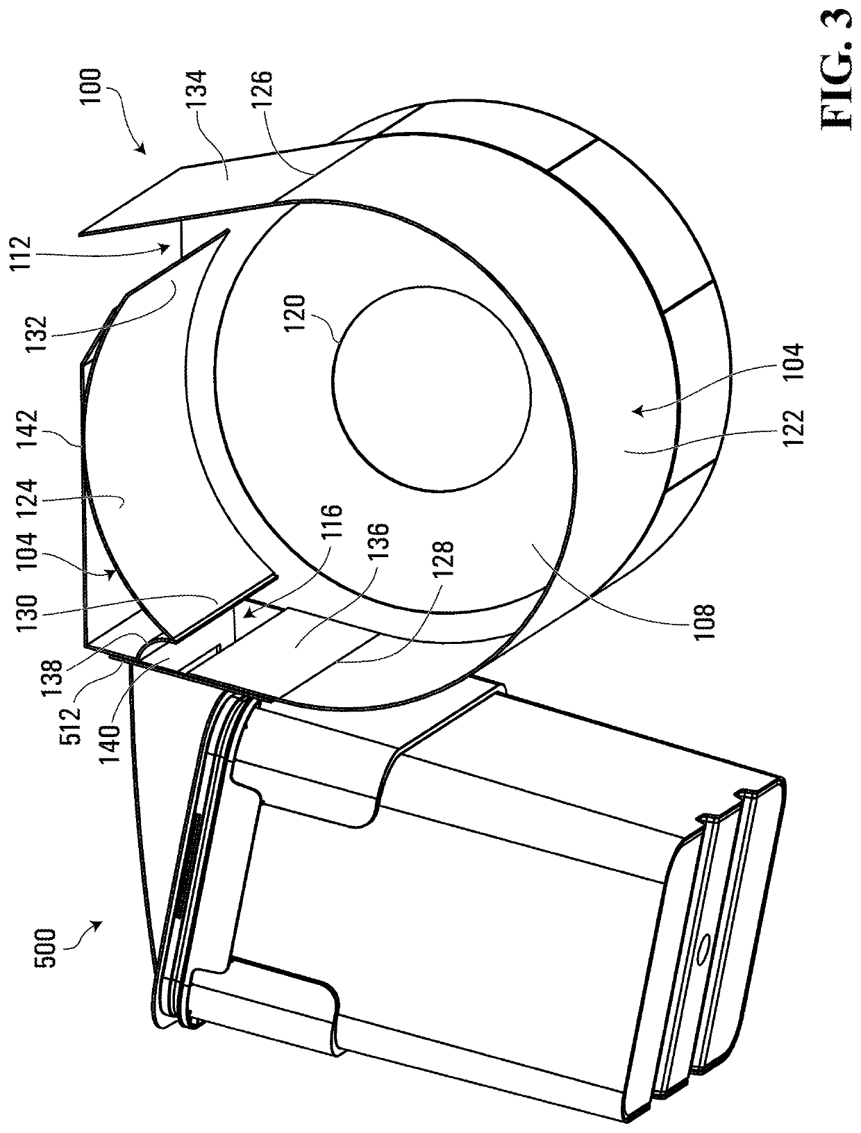
[0069]Referring to FIGS. 1 and 6, a centrifugal gas separator for separating gas and non-gas components of a gaseous stream, according to the invention, is shown generally at 600.

[0070]In this embodiment, the separator 600 includes all of the features of the separator 100 described above, and additionally includes a ramp 602 extending from the peripheral wall 104 and from a side wall of the separation chamber. More particularly, in this embodiment the side wall includes the end 110 of the chamber, which in the present embodiment is a solid aluminum side wall.

[0071]In this embodiment, the ramp 602 has a rectangular planar shape. More particularly, in this embodiment the ramp 602 has a square planar shape, and extends from the second wall segment 124 of the peripheral wall 104 and from the end 110, in a direction having both radially inward and axially inward components. In this embodiment, the ramp 602 is inclined, so that a normal to the plane of the ramp 602 is inclined about 45 de...

third embodiment

[0073]Referring to FIGS. 1 and 7, a centrifugal gas separator for separating gas and non-gas components of a gaseous stream, according to the invention, is shown generally at 700.

[0074]In this embodiment, the peripheral exhaust port 116 has been removed and replaced with a differently located peripheral exhaust port 702. In this embodiment the peripheral exhaust port 702 is disposed at a bottom of a peripheral wall 704, but in alternative embodiments, the peripheral exhaust port 702 may be defined through the peripheral wall 704 at any other location around its circumference. The peripheral wall 704 is identical to the peripheral wall 104 except for the location, shape and dimensions of the gap that defines the peripheral exhaust port. In this embodiment, the peripheral exhaust port 702 consists of a simple rectangular gap defined through the peripheral wall 104 of the separator 700.

[0075]In this embodiment, the separator 700 includes a diverter 706 extending from the peripheral wal...


PUM

PropertyMeasurementUnit
areaaaaaaaaaaa
diameteraaaaaaaaaa
volumeaaaaaaaaaa

Abstract

A centrifugal gas separator includes a separation chamber defined by a peripheral wall spaced apart from, extending around a central axis of and extending axially between opposite ends of the chamber. A peripheral intake port co-operates with the peripheral wall to introduce a rotating flow of a gaseous intake stream comprising a gas component and a non-gas component along an inside surface of the peripheral wall. A peripheral exhaust port defined through the peripheral wall diverts a radially outermost portion of the rotating flow, including at least some of the non-gas component, to exit the chamber. A gas component output port is configured to allow the gas component to be drawn from an axially central volume of the separation chamber.

Description

FIELD OF THE INVENTION[0001]The present invention relates to centrifugal gas separators, for separating the gas and non-gas components of a gaseous stream.BACKGROUND OF THE INVENTION[0002]Centrifugal gas separators are well known and are used in many different settings, to remove solids or liquids from air or from another gaseous intake stream. For example, in woodworking shops or sawmills, centrifugal gas separators are often used to remove sawdust and other airborne particles from the air in the work environment. Likewise, in certain agricultural applications such as the harvesting of hops for beer production or the harvesting of medical marijuana, a vacuum may be used to suck loose leaf material through openings in a tumbler, and a centrifugal gas separator may be used to remove the extracted leaf material from the air.[0003]The two most common forms of conventional centrifugal gas separators are cyclonic separators and Thien separators.[0004]A typical cyclonic separator consists...

Claims


Application Information

Patent Timeline
Patent Type & Authority Patents(United States)
IPC IPC(8): B01D45/12B04C3/06B01D45/16B04C5/04B04C5/13A47L9/16B04C3/00
CPCB04C3/06B01D45/16B01D45/12B04C5/04A47L9/1683B04C2003/006B04C5/13
Inventor INGRAM, ERIKKLOSSOK, RUDIHEYWOOD, JOE
Owner ETEROS TECH INC
Why Eureka
Try Eureka