Method and circuit for waveform generation

a waveform and circuit technology, applied in the field of circuits, can solve the problems of inability inability to fast enough clocked ncos to produce the bandwidth required by many applications, and many applications such as radars and ladars, and achieves simple switch and mixer networks, high controllability, and fast settling time

Inactive Publication Date: 2013-03-05
APPLIED SIGNALS INTELLIGENCE
View PDF1 Cites 2 Cited by
  • Summary
  • Abstract
  • Description
  • Claims
  • Application Information

AI Technical Summary

Benefits of technology

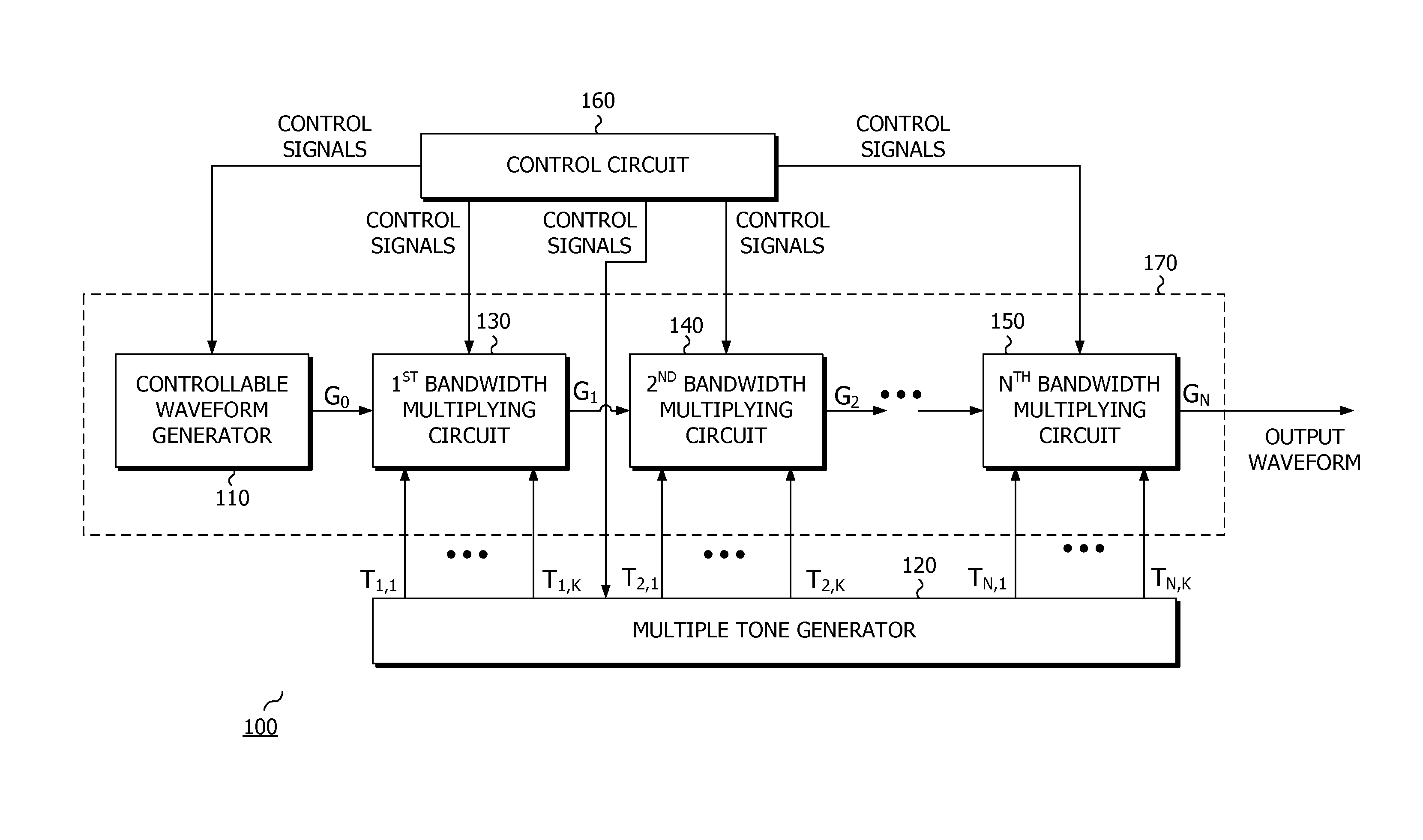
[0009]The disclosed apparatus uses small, inexpensive, low-power hardware to generate an initial signal spanning a narrow frequency range, with high controllability and extremely fast settling time to a an extremely stable state with low-phase noise and drift. One way to accomplish this is employing a direct digital synthesizer (DDS); another way is storing a complex pre-computed waveform in random access memory (RAM) and using a digital to analog converter (DAC) to generate the initial signal. The disclosed circuit then uses a relatively small number of additional parts to make a relatively small number of tones and relatively simple switch and mixer network to operate on the initial signal so as to produce an output signal covering a much wider frequency range with nearly equally fast settling time, high controllability, and low phase noise, as the initial source signal.
[0010]These additional parts extend the frequency range through a binary tree arrangement in order to minimize parts count. The binary tree is arranged, using high-side and low-side mixer injection to allow transitions between the tones to result in an output without transients. The combination of the binary tree and the specific frequencies chosen for the tones, and the arrangement of high and low side injection allows the entire output frequency range to be swept continuously without requiring any abrupt frequency changes from the initial signal generator. Since transients that cause filters to ring and not settle quickly are avoided, it also allows the hopping speed of the initial signal generator to be maintained across the entire extended output frequency range. By not requiring the initial signal to be multiplied, the controllability and low phase noise of the initial signal generator is maintained across the entire extended output frequency range.
[0011]Normally, an oscillator must be added every time the one extends the bandwidth by the bandwidth of the initial signal. For example, if the bandwidth of the initial signal was 100 MHz and the desired output bandwidth was 6.4 GHz, it would take 64 oscillators. Using the disclosed binary tree arrangement, every time a pair of oscillators is added, the output bandwidth is doubled. Using the disclosed method, the same 100 MHz initial bandwidth can be expanded to cover 6.4 GHz of bandwidth with only 12 oscillators. In general, if the ratio of output bandwidth to input bandwidth is 2N, then there is a factor of 2N / (2 log2(N)) reduction in the number of tones that must be generated and managed in a switching network. This reduction can significantly reduce the footprint and power required.

Problems solved by technology

Each method results in different sets of advantages and disadvantages in terms of metrics such as size, cost, weight, power consumption, settling time after a frequency change, modulation bandwidth, modulation linearity, long and short term stability, harmonic levels, spurious levels, and flexibility or ease of control.
Numerically controlled oscillators are well known to achieve optimally fast (short) settling times. At the same time, due to a combination of their discrete-time digitally-sampled stair-step output waveform, and the fact that the stair-step output levels must settle in each time-step period, an NCO cannot be clocked fast enough to produce the bandwidth required by many applications.
Many applications are extremely sensitive to spurious signals.
Applications such as radar, ladar (LAser Detection And Ranging), sonar, and numerous instrumentation applications, are fundamentally limited by the SFDR of the signals they generate and use to perform their function.
Harmonic and spurious signals correlate along with the desired signal, causing an error in the measured correlation, which is supposed to only come from the desired signal.
This method results in a high noise floor and is unsuitable for many applications.
Additionally, if the initial waveform was a complex waveform with, for example, a desired spectral notch, the multiplication process would destroy the notch.
This method results in a high power and a physically large and costly system that is incompatible with many applications.
The relatively slow switching speed of the PLL's in this solution, however, makes it unsuitable for many applications.

Method used


Image

  • Method and circuit for waveform generation
  • Method and circuit for waveform generation
  • Method and circuit for waveform generation

Examples


Embodiment Construction

[0038]The instant disclosure is provided to further explain in an enabling fashion the best modes of performing one or more embodiments of the present invention. The disclosure is further offered to enhance an understanding and appreciation for the inventive principles and advantages thereof, rather than to limit in any manner the invention. The invention is defined solely by the appended claims including any amendments made during the pendency of this application and all equivalents of those claims as issued.

[0039]It is further understood that the use of relational terms such as first and second, and the like, if any, are used solely to distinguish one from another entity, item, or action without necessarily requiring or implying any actual such relationship or order between such entities, items or actions. It is noted that some embodiments may include a plurality of processes or steps, which can be performed in any order, unless expressly and necessarily limited to a particular or...


PUM


Abstract

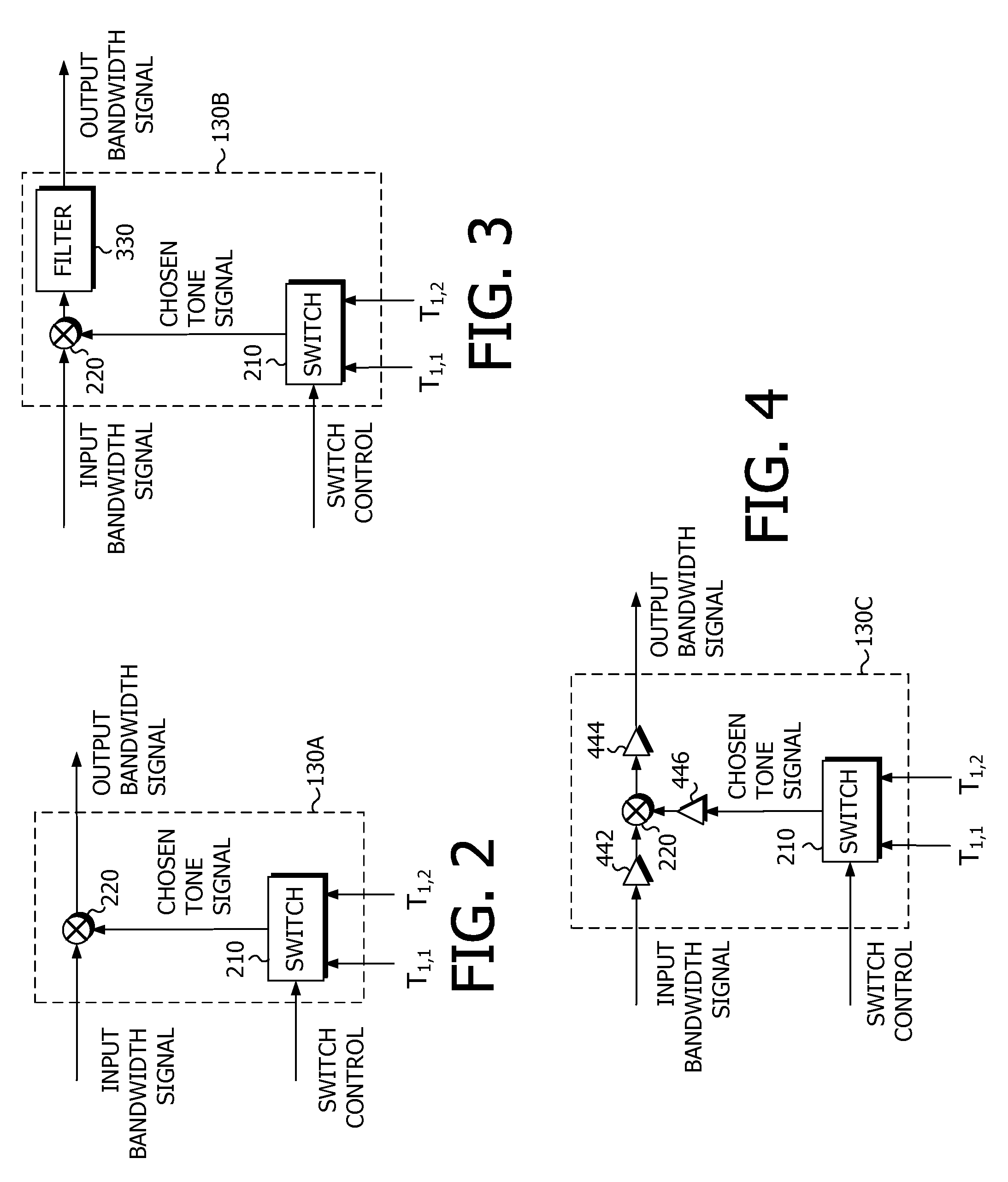
A programmable waveform generator, comprising: a controllable waveform generator configured to generate an initial bandwidth signal having an initial frequency bandwidth; a tone generator configured to generate a plurality of tone signals, each tone signal having a different frequency; a first bandwidth-multiplying circuit, including a first mixer having a first input port configured to receive the low-bandwidth signal; a first switch configured to choose one of the plurality of tone signals or a phase shifted version of one of the plurality of tone signals and output the chosen signal as a first chosen tone; a controller configured to control the operation of the bandwidth multiplying block, wherein the first mixer is further configured to receive the first chosen tone at a second input port, wherein the first mixer is further configured to mix the initial bandwidth signal and the first chosen tone to generate a first bandwidth signal at an output port, the first bandwidth signal having a first frequency bandwidth, wherein the first frequency bandwidth is greater than the initial frequency bandwidth, and wherein the first frequency bandwidth is an integer multiple of the initial frequency bandwidth.

Description

CROSS-REFERENCE TO RELATED PATENT DOCUMENTS[0001]This application relies for priority on U.S. provisional application Ser. No. 61 / 322,232, by John W. McCorkle, filed 8 Apr. 2010, entitled “METHOD AND CIRCUIT FOR WAVEFORM GENERATION,” the contents of which is hereby incorporated by reference in its entirety.FIELD OF THE INVENTION[0002]The disclosed circuitry relates to applications such as radar (RAdio Detection And Ranging), ladar (LAser Detection And Ranging), sonar, radio transmitters, radio receivers, and instrumentation such as spectrum analyzers, network analyzers. All of these applications require, high quality, signal generators that are able to switch a new frequency across wide bandwidths, and settle extremely quickly to a new extremely stable low-drift low-phase-noise frequency. In addition, the signal generators used in these applications are required to accurately sweep across a wide frequency range. This application relates high accuracy, low noise, small footprint, fas...

Claims


Application Information

Patent Timeline
Patent Type & Authority Patents(United States)
IPC IPC(8): H03B19/00
CPCH03B19/00H03B2200/0072H03B2200/008
Inventor MCCORKLE, JOHN W.
Owner APPLIED SIGNALS INTELLIGENCE
Why Eureka
Try Eureka