Electrolytic cell for heating electrolyte by a glow plasma field in the electrolyte

a technology of electrolyte and glow plasma, which is applied in the field of electrolyte heating cells, can solve the problems of reducing the ability of the plasma field to efficiently heat deeper electrolyte, deteriorating or eroding the electrode, and the inability to maintain the plasma field for an extended period

Active Publication Date: 2016-10-25
CORONA PLASMA SYST
View PDF13 Cites 0 Cited by
  • Summary
  • Abstract
  • Description
  • Claims
  • Application Information

AI Technical Summary

Benefits of technology

[0018]The following is an excerpt from an Intertek Laboratories Report dated Nov. 8, 2010, which provides third party evidence that the technology tested, (which is the subject of this application) produced results of 303% above unity. This is well within the range reported in “Nonlinear plasma dynamics in capacitive radio frequency discharges”.

Problems solved by technology

Secondly, the electrolyte can be heated by the plasma field.
This reduces the ability of the plasma field to efficiently heat deeper electrolyte.
And because the plasma field is below the plasma electrode, heat from the plasma field and heated electrolyte impinge against the electrode, deteriorating or eroding the electrode.
The plasma field cannot be maintained for an extended period and the plasma electrode requires frequent replacement, typically after only five or ten minutes of use.
Furthermore, it is difficult to control the output of the plasma field in a conventional electrolytic cell.

Method used


Image

  • Electrolytic cell for heating electrolyte by a glow plasma field in the electrolyte
  • Electrolytic cell for heating electrolyte by a glow plasma field in the electrolyte
  • Electrolytic cell for heating electrolyte by a glow plasma field in the electrolyte

Examples


Embodiment Construction

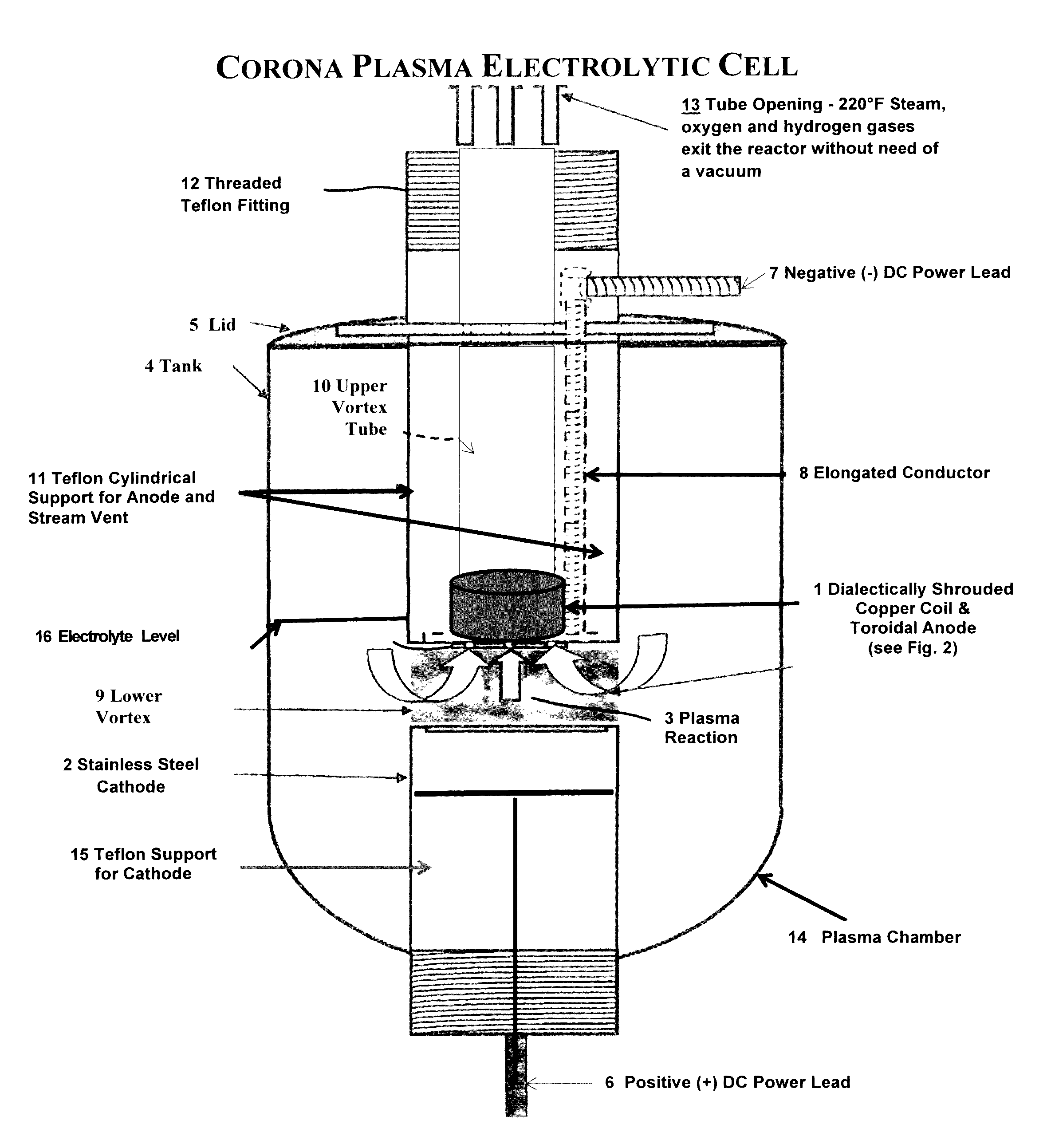
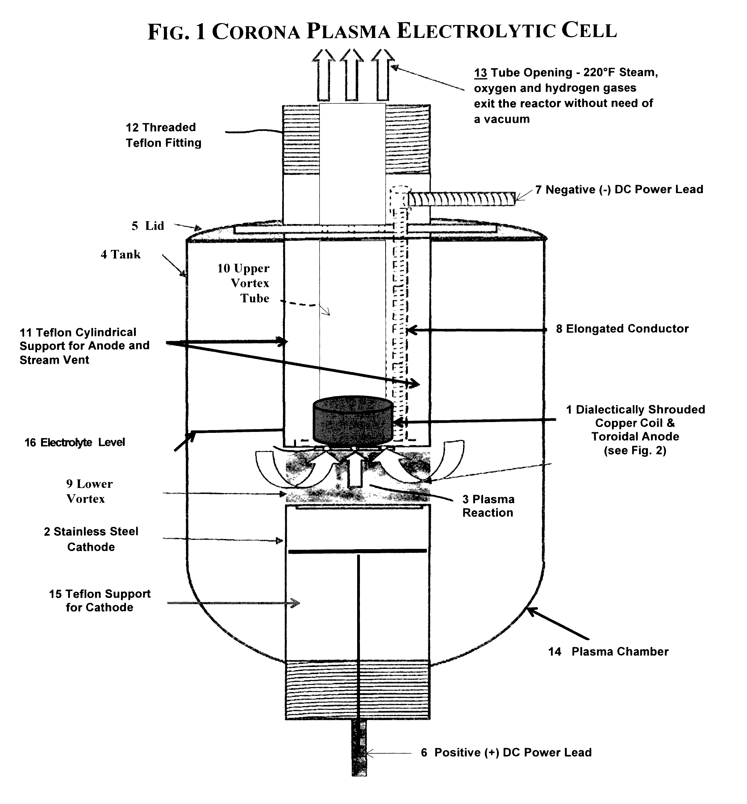
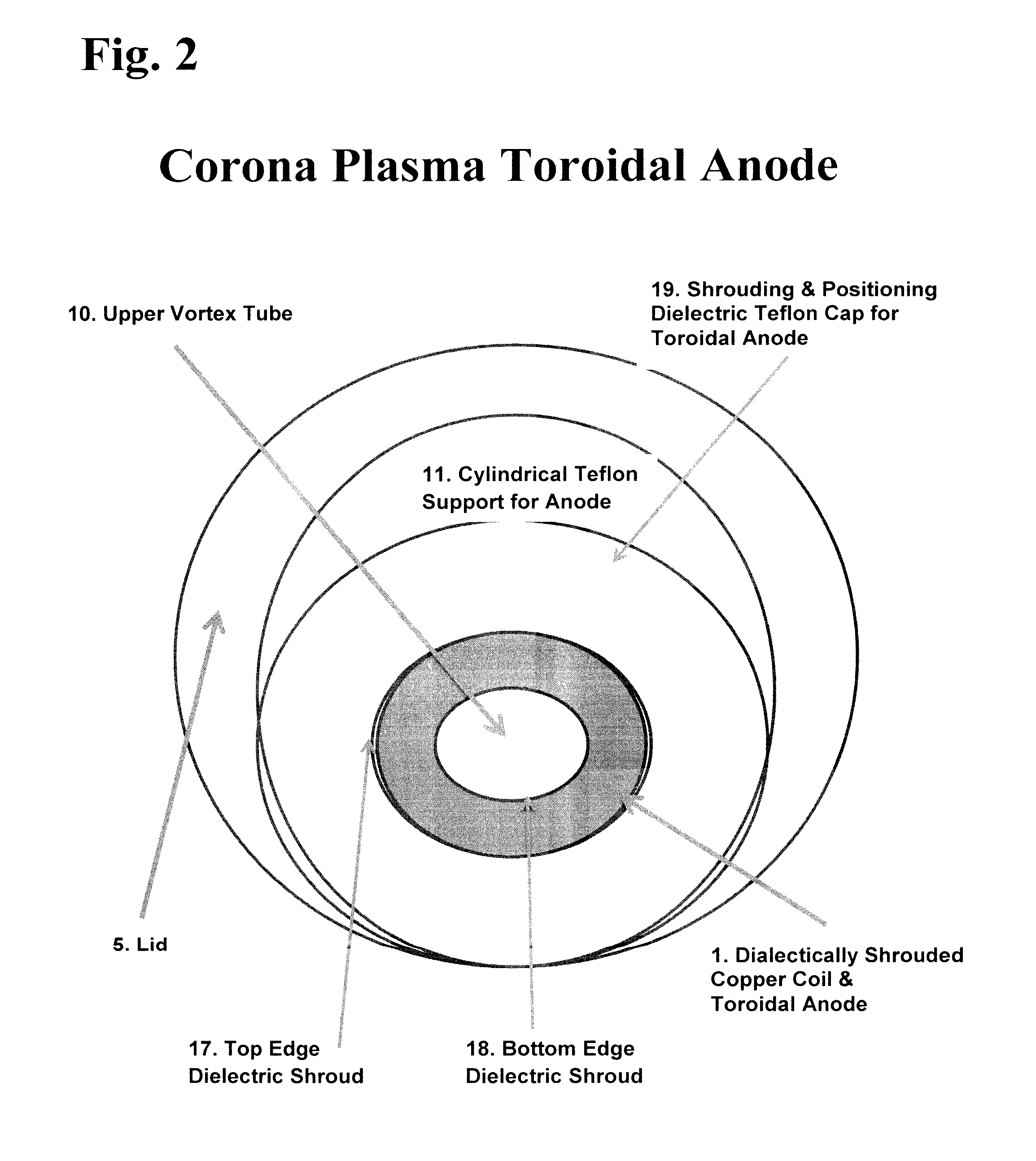
[0011]The present invention utilizes a Toroidal Anode 1 as the key element of a plasma confinement system including means for generating a Spheromark (easily formed, self-organized magnetized plasma configurations in the shape of a Torus), within a containment vessel identified as the Plasma Chamber 13 (or Tank 4 which is constructed of dielectric plastic), which comprises a plasma source with an anode 1 and a cathode 2 within the Plasma Chamber 13 and spaced apart 50 mm in a direction generally perpendicular to the magnetic lines of force of the plasma confinement system when an electric charge is applied between the Cathode 2 and Anode 1 The anode and cathode of the plasma source are arranged concentrically within the toroidal vessel with their axis coincident with the minor axis of the toroid. The anode 1 and cathode 2 each have a diameter of 76 mm, with the anode having a 10 mm Teflon shroud concealing the edge of the copper coil top 16 and bottom 17. Both electrodes are support...


PUM

PropertyMeasurementUnit
diameteraaaaaaaaaa
diameteraaaaaaaaaa
diameteraaaaaaaaaa

Abstract

An apparatus and method for generating a Contact Glow Plasma Discharge in an electrolyte such as 7% K2CO3. A Shrouded Toroidal Anode is partially submerged in the electrolyte directly above a Flat Torus Cathode (totally submerged in the electrolyte), spaced approximately 50 mm apart, and the two electrodes are arranged in a concentric manner. A potential difference is applied from the cathode to the anode causing gas to be formed on the cathode. This is followed by a contact glow plasma being formed on the surface of the cathode and electromagnetically confined by a Spheromark formed by the configuration of the electrodes. This confinement of the plasma prevents a plasma arc from consuming the anode, which in turn allows for the application of 12,000 Watts and the occurrence of “non-linear electron resonance heating”. The effects of nonlinear series resonance increase the total power dissipation by factors of 2-5 for low pressure capacitive plasmas. Thus explaining the 303% efficiency obtained with this apparatus.

Description

RELATED APPLICATIONS[0001]This application is a continuation-in-part of pending U.S. application Ser. No. 13 / 397,807 filed Feb. 16, 2012, which in turn is a continuation-in-part of Application No. PCT / US10 / 36983 filed Jun. 2, 2010, which in turn claims the benefit of U.S. Provisional Application No. 61 / 447,247 filed Feb. 28, 2011.TECHNICAL FIELD[0002]The present disclosure relates generally to electrolytic cells in which electrodes are in electrical contact with a liquid electrolyte. Specifically, the disclosure relates to an electrolytic cell for the generation of a plasma field in the electrolyte, and use of the electrolytic cell to generate heated electrolyte as a source of heat transfer.BACKGROUND ART[0003]Electrolytic cells that generate a plasma field in a liquid electrolyte are known. Such electrolytic cells are useful in different ways. First, they enable the study of the plasma field itself. Secondly, the electrolyte can be heated by the plasma field. The heated electrolyte...

Claims


Application Information

Patent Timeline
Patent Type & Authority Patents(United States)
IPC IPC(8): H01M8/243C25C7/02C25C7/00H05H1/42H05H1/24
CPCH05H1/24H05H1/2406H05H2001/2418H05H1/2418H05H1/247H05H1/2441
Inventor TIERNEY, DAVID MICHAELHOFFMAN, SR., RICHARD A.HOFFMAN, JR., JOHN E.PAGLIARO, II, JAMES J.
Owner CORONA PLASMA SYST
Why Eureka
Try Eureka