Sputtering sources for high-pressure sputtering with large targets and sputtering method

a high-pressure sputtering and target technology, applied in vacuum evaporation coatings, electrolysis components, coatings, etc., can solve the problem of almost impossible to push to the extent of cathode dark space below 1 cm, and achieve the effect of improving the stability of plasma, preventing flashover, and improving the quality of layers

Inactive Publication Date: 2016-11-01
FORSCHUNGSZENTRUM JULICH GMBH
View PDF26 Cites 0 Cited by
  • Summary
  • Abstract
  • Description
  • Claims
  • Application Information

AI Technical Summary

Benefits of technology

[0008]According to the invention, the magnetic north and the magnetic south of at least one magnetic field source, between which the stray magnetic field is formed, are located 10 mm or less, preferably 5 mm or less, and particularly preferably approximately 1 mm apart. The lower expedient limit for this distance is determined by the distance between the sputtering target and the sputtering plasma (cathode dark space). The magnetic field is intended to extend the path of electrons through the sputtering plasma so as to increase the likelihood for additional atoms of the sputtering gas to be ionized along this path. For this purpose, the field must extend through the cathode dark space into the sputtering plasma. The sputtering head according to the invention is intended to improve sputtering at high pressures of 0.5 mbar or more, preferably of 1 mbar or more. At such a high pressure, the cathode dark space typically extends over several tenths of a millimeter. So as to be able to influence the plasma, the magnetic field must overcome both this dark space and the distance from the target surface to the permanent magnet.
[0033]In the same manner as in the foregoing description of the sputtering heads, it is thus assured that the degree of ionization of the sputtering plasma, and consequently also the rate of material ablation from the target, can be locally adjusted. This improves the stability of the sputtering plasma and thus allows the use of larger sputtering targets, while achieving improved homogeneity of the layer thickness that is obtained on the substrate, in particular when, in an advantageous embodiment of the method, a sputtering head according to the invention is employed.

Problems solved by technology

At a sputtering gas pressure of 10−2 mbar or less, however, it is almost impossible to push to the extent of the cathode dark space below 1 cm, even when using very strong magnetic fields.

Method used


Image

  • Sputtering sources for high-pressure sputtering with large targets and sputtering method
  • Sputtering sources for high-pressure sputtering with large targets and sputtering method
  • Sputtering sources for high-pressure sputtering with large targets and sputtering method

Examples


Embodiment Construction

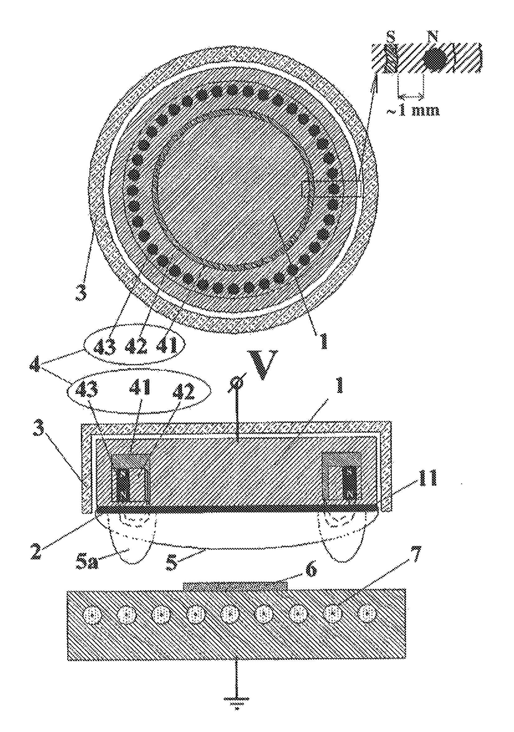
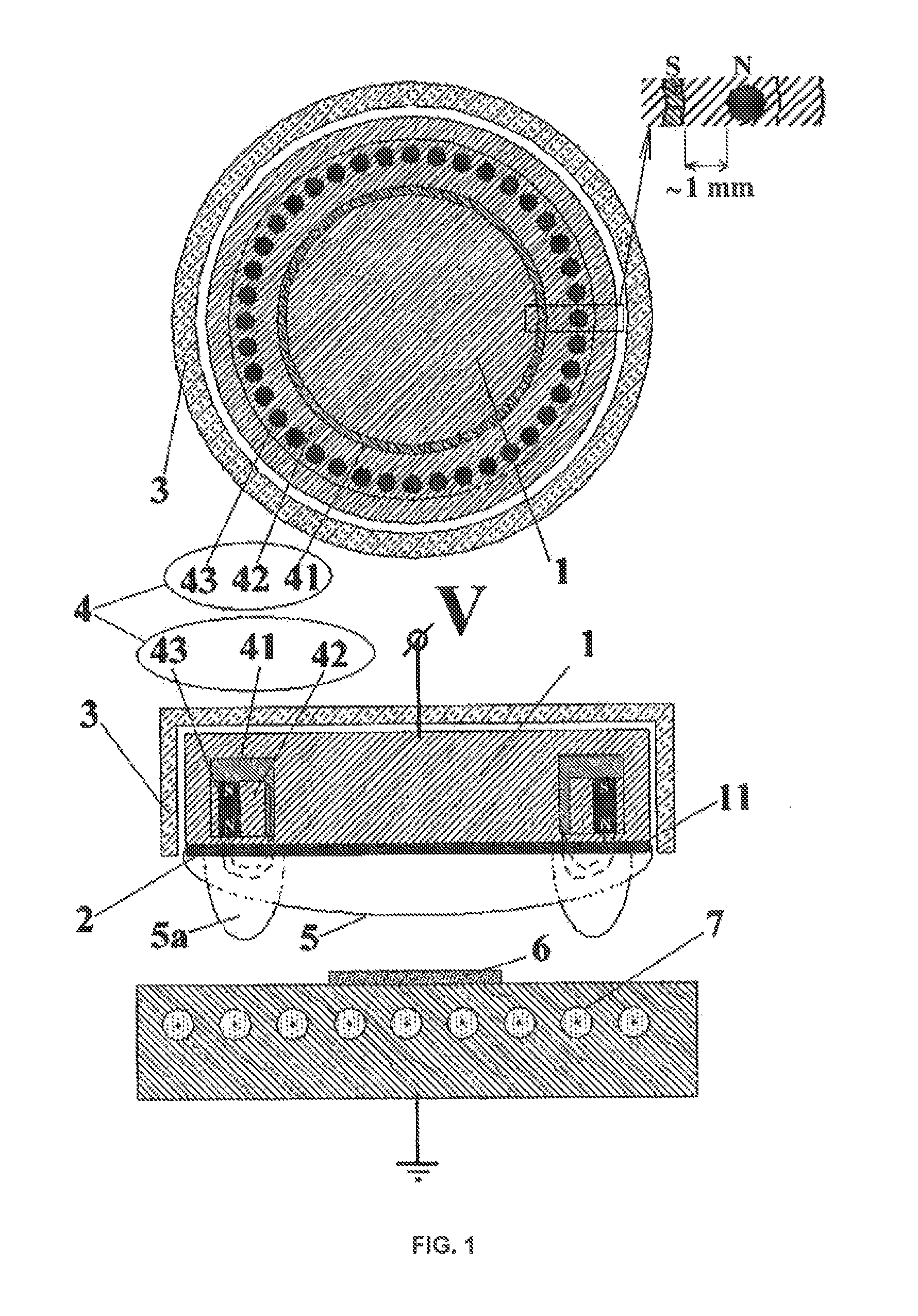
[0042]FIG. 1 schematically illustrates design of a sputtering source comprising an exemplary embodiment of the sputtering head according to the invention. The sputtering head is shown once in a sectional view with a plane that is parallel to the substrate surface and once in a sectional view with a plane that is rotated 90° thereto out of the drawing plane. The head includes a base body 1 comprising a target receiving area 11 for a sputtering target 2 measuring 50 mm in diameter. The base body 1, which can be connected to a potential V, is a water-cooled copper block. The base body, and thus also the target receiving area 11, are connected by a shield (not shown in FIG. 1) to ground potential and are arranged at a distance from this shield because of the solid state insulator 3. An annular arrangement 4 of magnetic field sources is located in the base body. This arrangement 4 comprises a peripheral yoke ring 41 that is made of iron and includes a cut-out in which a carrier ring 42 m...


PUM

PropertyMeasurementUnit
pressureaaaaaaaaaa
distanceaaaaaaaaaa
distanceaaaaaaaaaa

Abstract

A sputtering head comprises a receiving area for a sputtering target (target receptacle). The sputtering head comprises one or more magnetic field sources so as to generate a stray magnetic field. The magnetic north and the magnetic south of at least one magnetic field source, between which the stray field forms, are located 10 mm or less, preferably 5 mm or less, and particularly preferably approximately 1 mm apart. It was found that, notably when sputtering at a high sputtering gas pressure of 0.5 mbar or more, the degree of ionization of the sputtering plasma, and consequently also the ablation rate of the sputtering target, can be locally adjusted by such a locally effective magnetic field. This allows the thicknesses of the layers that are obtained to be more homogeneous over the surface of the substrate. Advantageously, the sputtering head additionally comprises a solid state insulator, which surrounds the base body comprising the target receptacle and the sputtering target (all connected to potential) and electrically insulates the same from the shield that spatially limits the material ablation to the sputtering target (connected to ground).

Description

BACKGROUND OF THE INVENTION[0001]During sputtering, a vacuum is first produced in a sputtering chamber, and then an atmosphere of a sputtering gas having a defined pressure is created. A gas discharge of the sputtering gas is ignited in the vicinity of a sputtering target that is attached to a sputtering head and generally kept at a negative potential. A sputtering plasma comprising positively charged ions and free electrons is created from the electrically neutral atoms or molecules of the sputtering gas. The positively charged ions are accelerated by the negative potential of the target on the surface thereof and there, by way of momentum transfer, knock out material, some of which travels in the direction of the substrate to be coated as a result of rebound and is deposited there. At the same time, these ions release electrons from the target as a result of this bombardment, which are accelerated by the electric field in the direction of the sputtering plasma and there ionize fur...

Claims


Application Information

Patent Timeline
Patent Type & Authority Patents(United States)
IPC IPC(8): C23C14/34C23C14/56C23C14/35H01J37/34
CPCC23C14/35C23C14/562H01J37/3408H01J37/3452
Inventor FALEY, MIKHAILPOPPE, ULRICH
Owner FORSCHUNGSZENTRUM JULICH GMBH
Why Eureka
Try Eureka