Floating clamping device for injection head of continuous oil pipe

a technology of continuous oil pipe and clamping device, which is applied in the direction of drilling rods, drilling pipes, drilling casings, etc., can solve the problems of compromising the flexibility of the injector head, damage to the oil pipe or machine, etc., and achieves the effect of better clamping

Active Publication Date: 2016-11-15
YANTAI JEREH OILFIELD SERVICES GROUP +1
View PDF3 Cites 120 Cited by
  • Summary
  • Abstract
  • Description
  • Claims
  • Application Information

AI Technical Summary

Benefits of technology

[0005]The present invention has the following beneficial effects: since a clamping assembly with rollers is used and the rollers utilize the pushing plate as a track to move, the clamping assembly can move steadily, and the structure of the pushing plate is very simple; in addition, since the rollers employ ceramic rolling shaft sleeves and don't have lubrication requirement, the injector head moves more reliably and is easy to service and operate; since the connection with the pushing plate is flexible, the pushing plate can float on the angle or position as the position of the continuous oil pipe changes, and therefore the continuous oil pipe is stressed uniformly and will not be hard extruded, and any damage to the machine can be avoided; moreover, since the pushing plate structure is simplified, the entire clamping device has compact structure and small size. In summary, the floating clamping device for injector head of continuous oil pipe can be used in injector head apparatuses for continuous oil pipes, and will have no deformation or abrasion resulted from uneven clamping force; thus, the oil tube clamping effect can be improved, and a technical problem of misalignment to the well mouth during the operation of injector head for continuous oil pipe in the prior art is solved.
[0018]A beneficial effect of the above refined scheme is: better clamping effect can be attained.

Problems solved by technology

The structure described above have the following drawbacks in actual application: the pushing plate with bearings has poor maintainability, and is difficult to replace or repair; in addition, the clamping block seat that slides on the bearings may be worn easily and is difficult to replace; moreover, since the pushing plate is not fixed flexibly on the supporting plate, the pushing plate may be offset and seized, and therefore the clamping block is not stressed evenly and may be worn severely, causing damages to the oil pipe or machine; furthermore, since the pushing plate carries bearing bracket and bearings, the clamping device in such a structure is large in size, and even the clamping oil cylinders have to be mounted outside of the chain ring; consequently, the flexibility of the injector head is compromised.

Method used


Image

  • Floating clamping device for injection head of continuous oil pipe
  • Floating clamping device for injection head of continuous oil pipe
  • Floating clamping device for injection head of continuous oil pipe

Examples


Embodiment Construction

[0025]Hereunder the embodiments of the present invention will be detailed, with reference to the accompanying drawings.

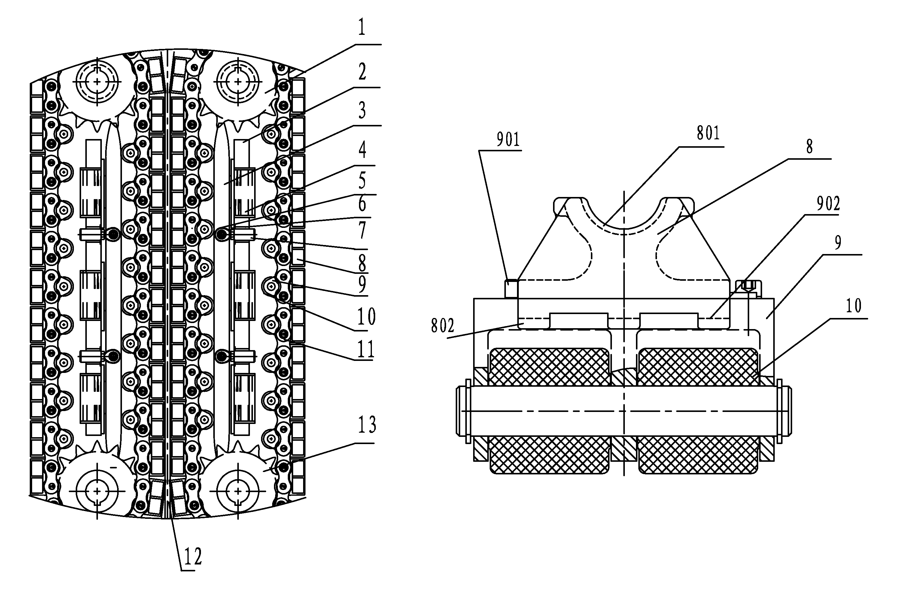
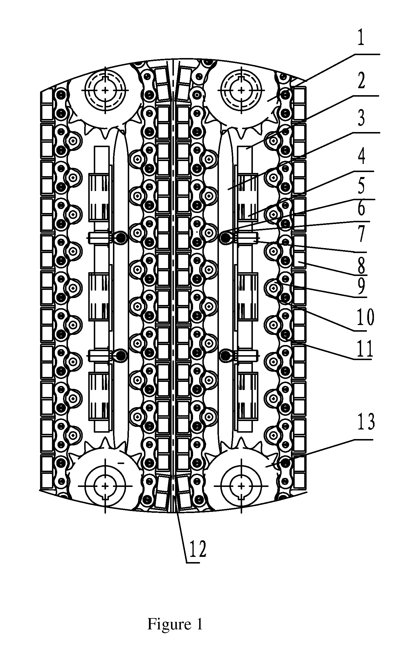
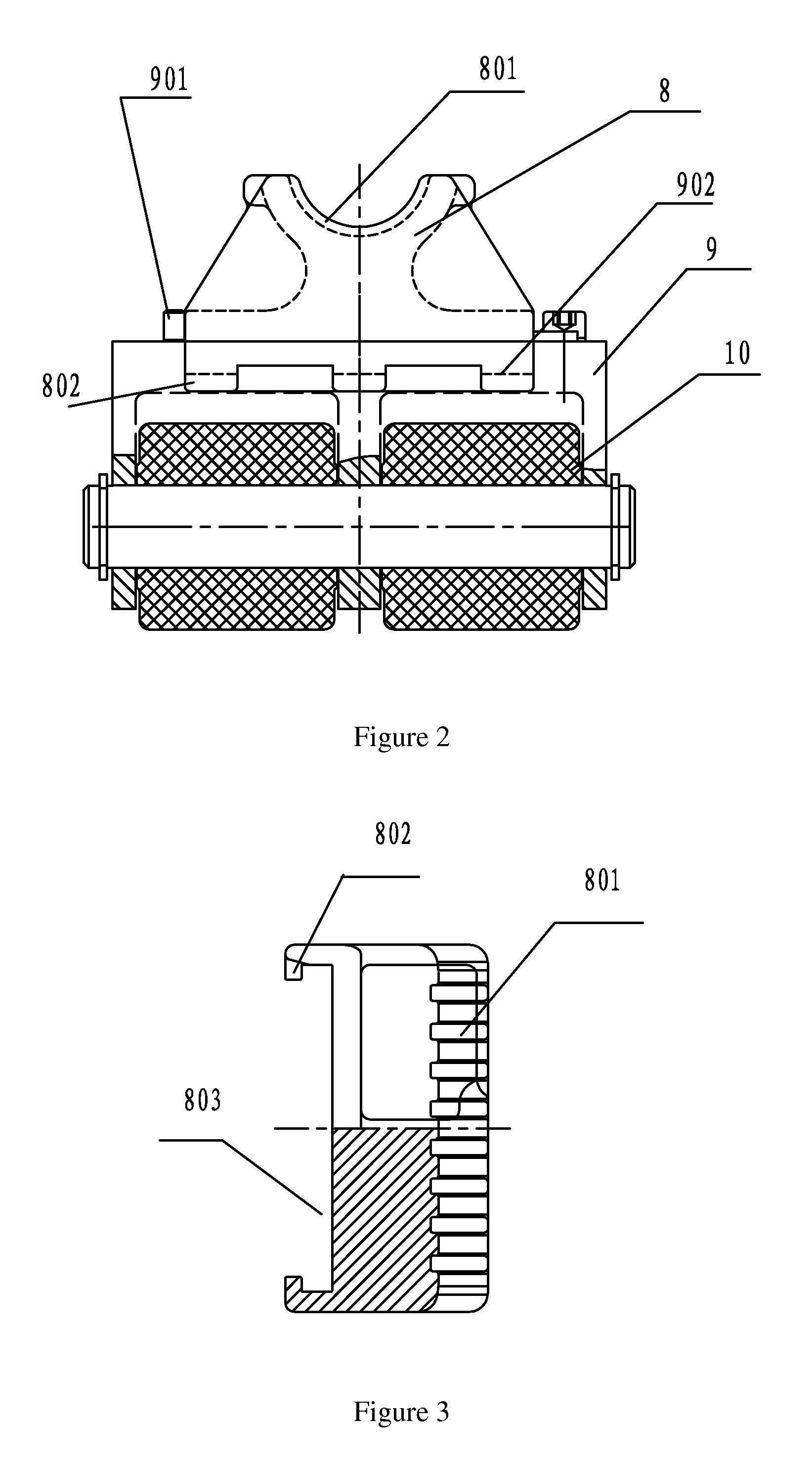
[0026]As shown in FIG. 1-5, the present invention provides a floating clamping device for injector head of continuous oil pipe, comprising a drive sprocket 1, a transmission chain 11, a supporting plate 2, a pushing plate 3, clamping oil cylinders 4, and a clamping assembly. Three clamping oil cylinders 4 are installed on the supporting plate 2 fixedly, the pushing plate 3 is fixed to the supporting plate 2 via a pin shaft 7, one end of the pin shaft is connected to the pushing plate 3 via a spherical plain bearing 5, and the other end of the pin shaft is mounted in a shaft sleeve 6 on the supporting plate 2 fixedly. With the spherical plain bearing 5, the degree of freedom of the pushing plate 3 is increased, and the pushing plate 3 floats more flexibly. The clamping assembly comprises a saddle-shaped clamping block 8, a clamping block seat 9, and rollers 10 mounte...


PUM


Abstract

A floating clamping device for an injection head of a continuous oil pipe, including a drive sprocket, a transmission chain, a supporting plate, a pushing plate, clamping oil cylinders and a clamping assembly. At least two clamping oil cylinders are installed on the supporting plate fixedly. The pushing plate is fixed on the supporting plate through a pin shaft. The clamping assembly includes a saddle-shaped clamping block, a clamping block seat and rollers which are mounted on the clamping block seat. The clamping assembly is mounted on the transmission chain. A piston rod of the clamping oil cylinder is pressed on one face of the pushing plate, while the other face of the pushing plate is pressed on the rollers. The pushing plate has a simple structure and is convenient for maintenance; the clamping device has a compact structure and a reduced volume.

Description

FIELD OF THE INVENTION[0001]The present invention relates to the domain of petroleum drilling and production equipment, in particular to a floating clamping device for injection head of continuous oil pipe.BACKGROUND OF THE INVENTION[0002]Continuous oil pipe operation apparatuses are widely applied in different tasks in oil and gas field exploration and development. In recent years, as the usage and applied range of injection heads of continuous oil pipes were extended continuously, the operability and maintainability of injection heads of continuous oil pipes have become more and more important. A holding device for injector head of continuous oil pipe is a key component for continuous oil pipe operation apparatuses, in which the sprocket is driven by a hydraulic motor that can rotate in normal direction / reversed direction, and the continuous oil pipe is clamped by the clamping assembly between the chain links, so that the continuous oil pipe moves with the chain; thus, the continu...

Claims


Application Information

Patent Timeline
Patent Type & Authority Patents(United States)
IPC IPC(8): E21B19/22
CPCE21B19/22
Inventor LIU, DONGYU, QINGFENGFANG, JILEI
Owner YANTAI JEREH OILFIELD SERVICES GROUP
Why Eureka
Try Eureka