Mirror for the EUV wavelength range, substrate for such a mirror, projection objective for microlithography comprising such a mirror or such a substrate, and projection exposure apparatus for microlithography comprising such a projection objective

a technology of ultraviolet light and mirror, which is applied in the direction of lighting and heating apparatus, photomechanical apparatus, instruments, etc., can solve the problems of euv light transmitting too much to the substrate, affecting the euv light transmission rate, and not constant reflectivity in the specified angle of incidence interval, so as to prevent the irreversible change in the volume of the substrate

Active Publication Date: 2016-11-15
CARL ZEISS SMT GMBH
View PDF22 Cites 0 Cited by
  • Summary
  • Abstract
  • Description
  • Claims
  • Application Information

AI Technical Summary

Benefits of technology

[0008]Therefore, it is an object of the invention to provide a mirror for the EUV wavelength range which, even at high doses of EUV light, has a high long-term stability of its optical properties during the operating period of from a few months to a few years.
[0051]Yet another formulation of the present invention provides a substrate for a mirror for the EUV wavelength range, wherein at least one surface protecting layer SPL or at least one surface protecting layer system SPLS having a thickness of greater than 20 nm, in particular of greater than 50 nm, is provided on the substrate for preventing an irreversible alteration of the surface of the substrate under EUV radiation of more than 0.1 nm measured in the normal direction at a location within the irradiated region of the substrate relative to the surface of the substrate at a location outside the irradiated region measured in the same direction, and at the same time for exerting a tensile stress for compensation of layer stresses of further layers to be applied on the substrate.

Problems solved by technology

What is disadvantageous about the abovementioned layers, however, is that their reflectivity in the angle of incidence interval specified is not constant, but rather varies.
A variation of the reflectivity of a mirror over the angles of incidence is disadvantageous, however, for the use of such a mirror at locations with high angles of incidence and with high angle of incidence changes in a projection objective for microlithography since such a variation leads for example to an excessively large variation of the pupil apodization of such a projection objective.
What is furthermore disadvantageous about the abovementioned layers is that the latter transmit too much EUV light to the substrate, as a result of which the substrate is exposed to high doses of EUV light over a long period of time.
In the case of generally non-uniform irradiation of the mirrors, said densification leads to a non-uniform change in their surface form, as a result of which the optical imaging properties of the mirrors are changed in an undesirable manner during the operating period.

Method used


Image

  • Mirror for the EUV wavelength range, substrate for such a mirror, projection objective for microlithography comprising such a mirror or such a substrate, and projection exposure apparatus for microlithography comprising such a projection objective
  • Mirror for the EUV wavelength range, substrate for such a mirror, projection objective for microlithography comprising such a mirror or such a substrate, and projection exposure apparatus for microlithography comprising such a projection objective
  • Mirror for the EUV wavelength range, substrate for such a mirror, projection objective for microlithography comprising such a mirror or such a substrate, and projection exposure apparatus for microlithography comprising such a projection objective

Examples


Embodiment Construction

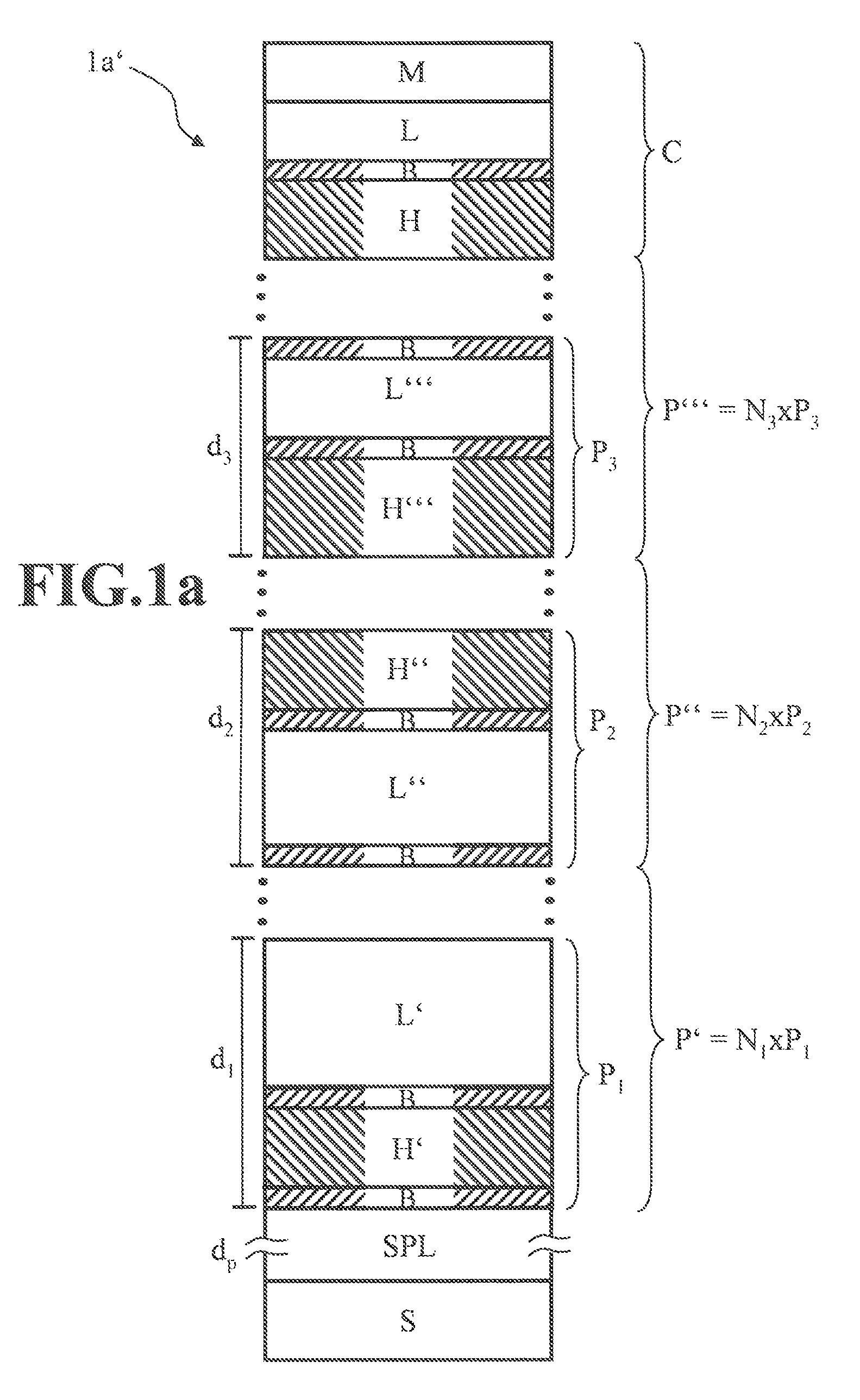
[0076]Respective mirrors 1a, 1a′, 1b, 1b′, 1c and 1c′ embodying aspects of the invention are described below with reference to FIGS. 1, 1a, 2, 2a, 3 and 3a, the corresponding features of the mirrors bearing the same reference signs in the figures. Furthermore, the corresponding features or properties of these mirrors according to aspects of the invention are explained in summary for FIGS. 1 to 3a below following the description concerning FIG. 3a.

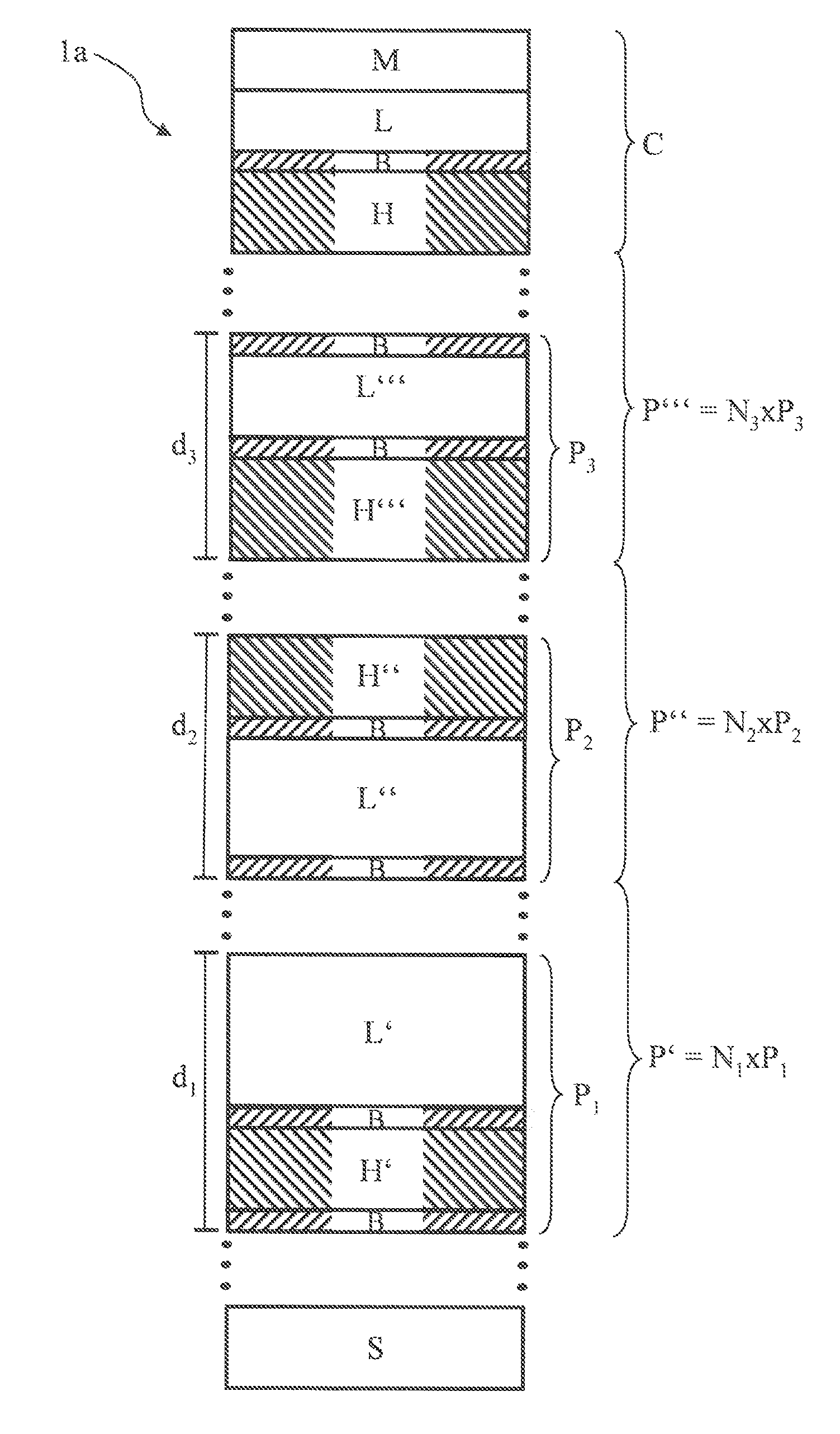
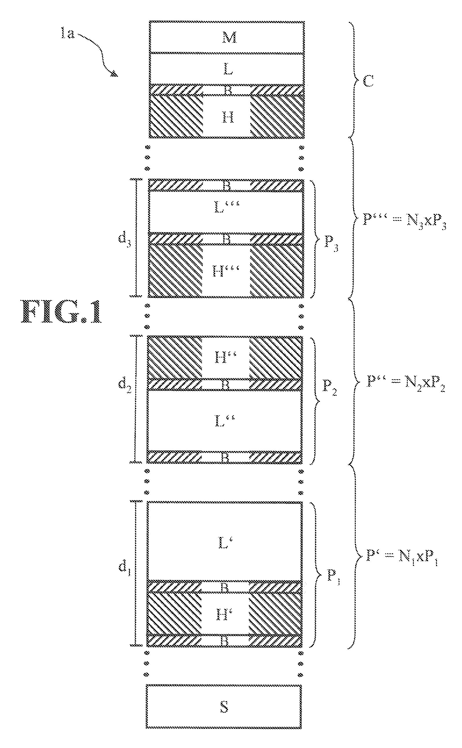
[0077]FIG. 1 shows a schematic illustration of a mirror 1a according to the invention for the EUV wavelength range comprising a substrate S and a layer arrangement. In this case, the layer arrangement comprises a plurality of surface layer systems P′, P″ and P′″ each consisting of a periodic sequence of at least two periods P1, P2 and P3 of individual layers, wherein the periods P1, P2 and P3 comprise two individual layers composed of different materials for a high refractive index layer H′, H″ and H′″ and a low refractive index layer L′, ...


PUM

PropertyMeasurementUnit
thicknessaaaaaaaaaa
thicknessaaaaaaaaaa
thicknessaaaaaaaaaa

Abstract

A mirror (1a; 1a′; 1b; 1b′; 1c; 1c′) for the EUV wavelength range and having a substrate (S) and a layer arrangement, wherein the layer arrangement includes at least one surface layer system (P′″) consisting of a periodic sequence of at least two periods (P3) of individual layers, wherein the periods (P3) include two individual layers composed of different materials for a high refractive index layer (H′″) and a low refractive index layer (L′″), wherein the layer arrangement includes at least one surface protecting layer (SPL, Lp) or at least one surface protecting layer system (SPLS) having a thickness of greater than 20 nm, and preferably greater than 50 nm.

Description

CROSS REFERENCE TO RELATED APPLICATIONS[0001]This application is a Continuation of International Application No. PCT / EP2010 / 067003, filed on Nov. 8, 2010, which was published under PCT Article 21(2) in English, and which claims the benefit of German Application No. 10 2009 054 653.7, filed Dec. 15, 2009. The entire disclosures of each of these applications are hereby incorporated into the present Continuation Application by reference.FIELD OF AND BACKGROUND OF THE INVENTION[0002]The invention relates to a mirror for the extreme-ultraviolet (EUV) wavelength range and a substrate for such a mirror. Furthermore, the invention relates to a projection objective for microlithography comprising such a mirror or such a substrate. Moreover, the invention relates to a projection exposure apparatus for microlithography comprising such a projection objective.[0003]Projection exposure apparatuses for microlithography for the EUV wavelength range have to rely on the assumption that the mirrors us...

Claims


Application Information

Patent Timeline
Patent Type & Authority Patents(United States)
IPC IPC(8): G02B5/08G03F7/20G02B1/10B82Y30/00
CPCG02B5/0891B82Y30/00G02B1/10G02B5/0816G03F7/70233G03F7/70316G03F7/70958G02B1/14B82Y20/00
Inventor MUELLENDER, STEPHANWEBER, JOERNCLAUSS, WILFRIEDPAUL, HANS-JOCHENBRAUN, GERHARDMIGURA, SASCHADODOC, AURELIANZACZEK, CHRISTOPHVON BLANCKENHAGEN, GISELALOERCHER, ROLAND
Owner CARL ZEISS SMT GMBH
Why Eureka
Try Eureka