
Two-piece valve stem seal

a valve stem and valve stem technology, applied in the direction of engine seals, valve arrangements, sealing arrangements, etc., can solve the problems of valve stem seal failure, spring seat rigidity and not flexible, cracking or breaking of spring seats, etc., to achieve the effect of reducing stress concentration, reducing stress concentration, and reducing biasing for

Inactive Publication Date: 2016-11-22
FREUDENBERG NOK GEN PARTNERSHIP
View PDF35 Cites 6 Cited by
  • Summary
  • Abstract
  • Description
  • Claims
  • Application Information

AI Technical Summary

Benefits of technology

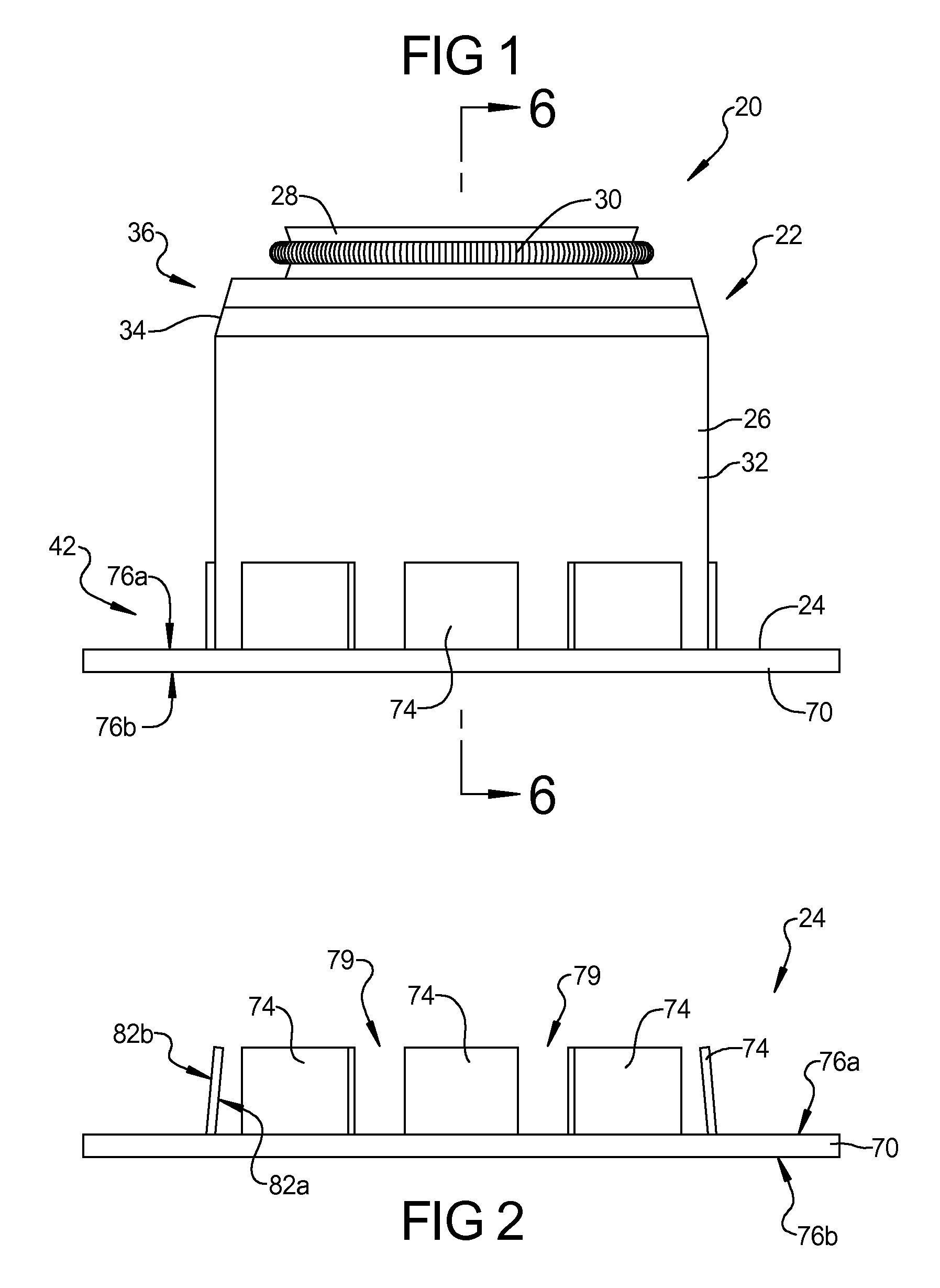
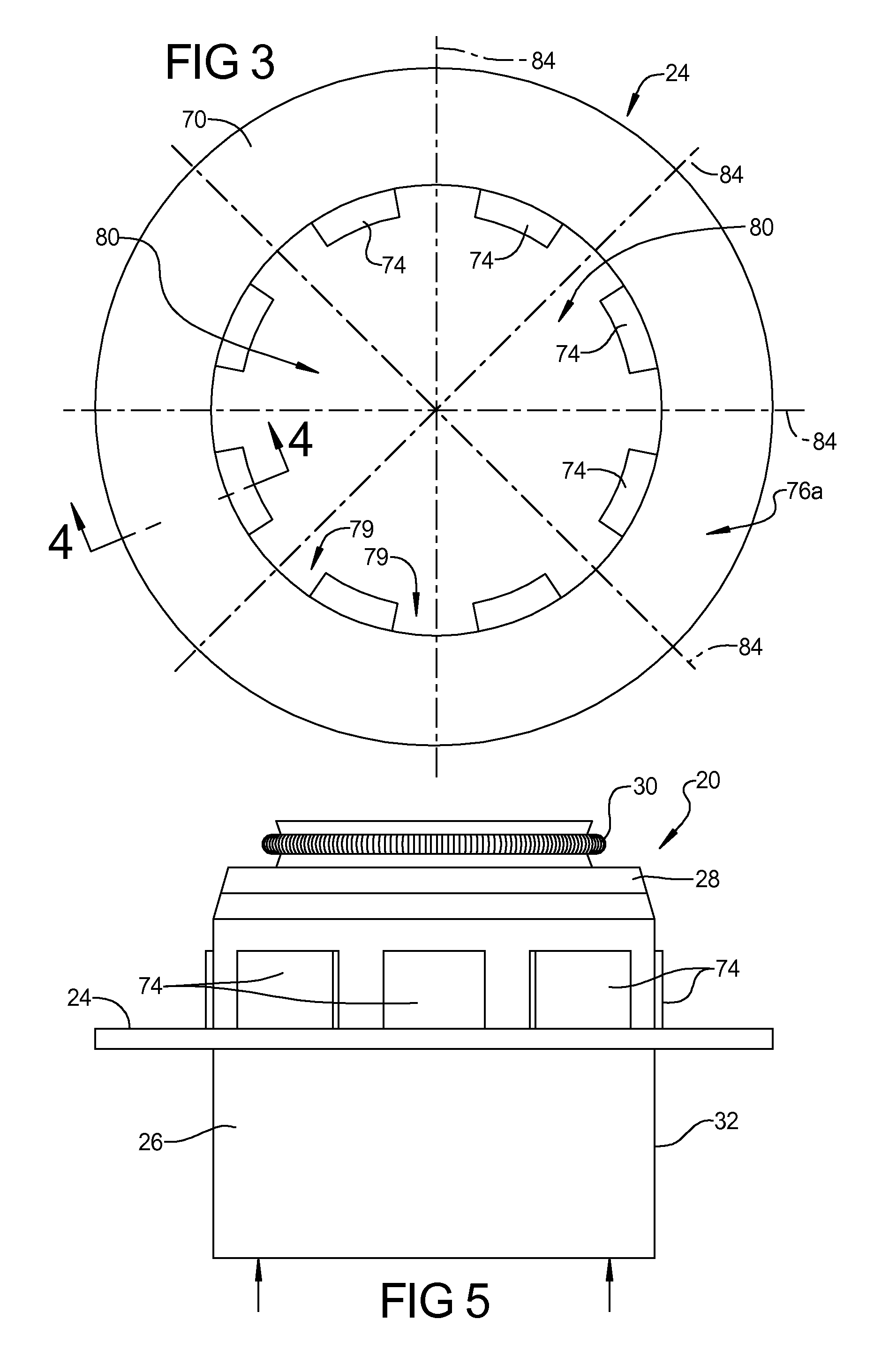
[0003]The primary function of a valve stem seal in an internal combustion engine, for example, is to allow adequate lubrication at the valve stem / valve guide interface while minimizing internal oil consumption. A valve stem seal assembly generally includes a rigid shell structure and a seal body, with the assembly having a generally hollow interior adapted to receive a valve stem guide. Typically, the shell structure supports the seal body, which surrounds the valve stem in order to essentially “meter” the provision of oil for lubricating the valve guide's inner diameter and the outer diameter of the valve stem. At the same time, however, the valve stem seal serves to minimize the amount of oil that can be drawn into the combustion chamber or pass to the engine's exhaust.
[0049]Thus, valve stem seals according to the present teachings can have reduced stress concentrations such that an increased useful life may be realized and / or less material utilized while still providing a robust seal. Additionally, valve stem seals according to the present teachings may also result in a reduction in dimensional tolerance requirements for the various components such that reduce manufacturing costs may be achieved.

Problems solved by technology

The interface between the can and the spring seat is generally rigid and not flexible.
This rigid interface results in stress concentrations that can cause cracking or breaking of the spring seat during vehicle operations due to resonance conditions caused by valvetrain harmonics.
During resonance conditions, the force of the spring on the spring seat can exceed the design specifications such that fatigue and cracking of the spring seat can occur, resulting in failure of the valve stem seal.
While it may be possible to design the valve stem seal to a degree that can accommodate the forces associated with a resonance condition, such valve stem seal would have a significantly greater cost.
The high tolerance requirement increases the costs of the valve stem seal.

Method used


Image

  • Two-piece valve stem seal
  • Two-piece valve stem seal
  • Two-piece valve stem seal

Examples


second embodiment

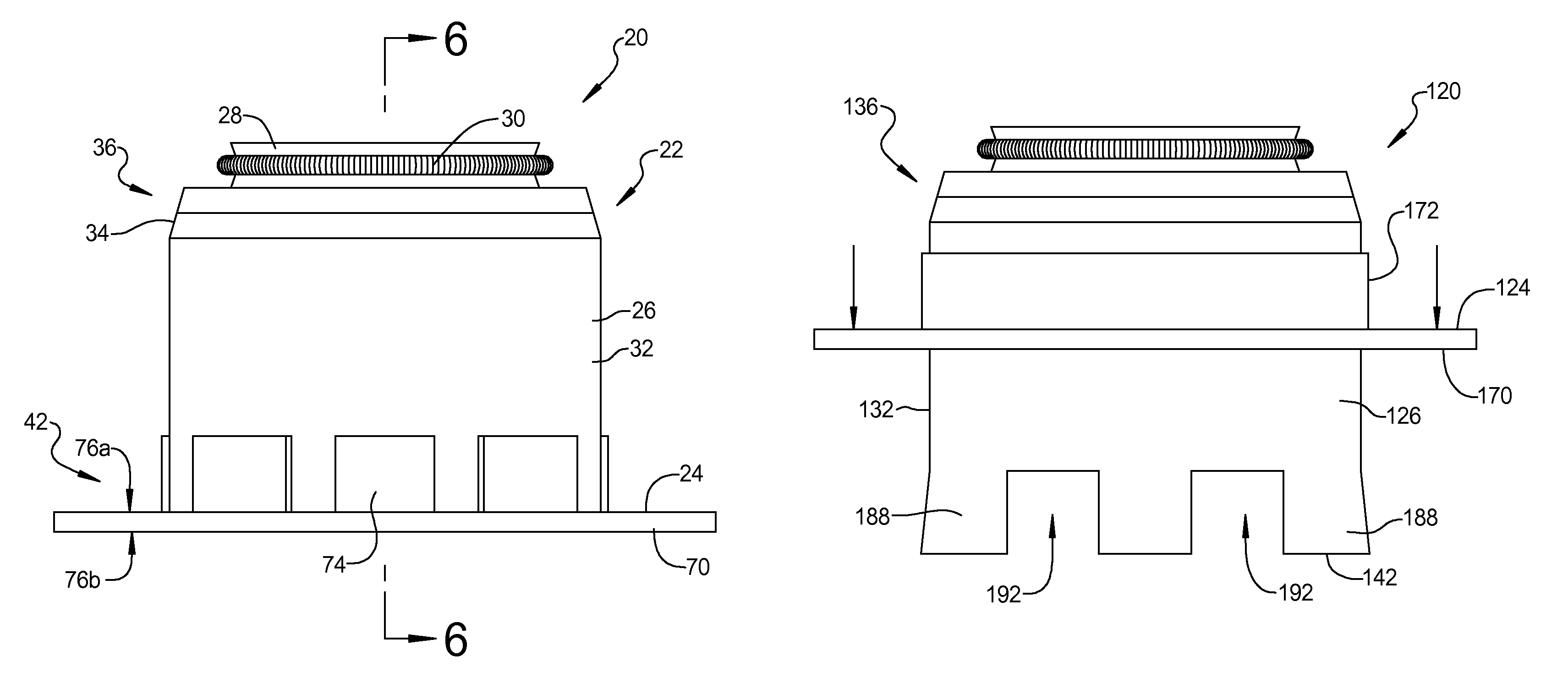
[0036]Referring now to FIGS. 7-10, a valve stem seal 120 according to the present teachings is shown. Valve stem seal 120 is similar to valve stem seal 20 discussed above. As such, only the main differences will be described herein. Valve stem seal 120 includes a can assembly 122 that includes a can 126, a seal body 128, and a spring 130 that is assembled onto a spring seat 124. In valve stem seal 120, spring seat 124 does not include fingers. Rather, spring seat 124 includes an axially extending annular ring portion 172 that extends from flange portion 170 and surrounds opening 180. Annular portion 172 and flange portion 170 are an integral one-piece construction and are substantially rigid such that only minimal or negligible flexing between annular portion 172 and flange portion 170 occurs. Spring seat 124 may be hardened while can 126 may be non-hardened to allow some flexibility, as described below.

[0037]In valve stem seal 120, second end 142 of can 126 includes a plurality of ...

third embodiment

[0041]Referring now to FIGS. 11-14, a valve stem seal 220 according to the present teachings is shown. Valve stem seal 220 is similar to valve stem seals 20 and 120 described above. As such, only the main differences are described herein. Valve stem seal 220 includes a can assembly 222 with a can 226, seal body 228 and spring 230. A spring seat 224 is attached to can assembly 222 to form valve stem seal 220.

[0042]In valve stem seal 220, spring seat 224 includes a plurality of spring fingers 274 extending axially upwardly from flange portion 270 while can 226 also includes a plurality of axially downwardly extending spring fingers 288 adjacent second end 242. Similar to valve stem seals 20, 120 discussed above, fingers 274 on spring seat 224 are biased radially inwardly while fingers 288 on can 226 are biased radially outwardly. Thus, in this embodiment, both can 226 and spring seat 224 include respective fingers 288, 274 thereon with respective gaps 292, 279 therebetween.

[0043]The w...


PUM


Abstract

A valve stem seal utilizes a multi-piece construction to reduce the required manufactured tolerances and / or improve the stress handling capabilities. The valve stem seal can include a first member or can which can be assembled to a second member or spring seat. The can and / or spring seat can have a plurality of axially extending resilient fingers that are biased such that when assembled the fingers are bent against the bias due to the engagement between the can and the spring seat. The fingers on the spring seat allow the spring seat to bend or move relative to the can to accommodate the loading of a valve spring on the spring seat. The use of resilient fingers on the can and / or the spring seat reduces the manufacturing tolerances required for the valve stem seal.

Description

FIELD[0001]The present disclosure relates to valve stem seals and, more particularly, to a two-piece valve stem seal, such as those used in an internal combustion engine but applicable to other valve stem sealing applications.BACKGROUND AND SUMMARY[0002]This section provides background information related to the present disclosure which is not necessarily prior art. This section also provides a general summary of the disclosure, and is not a comprehensive disclosure of its full scope or all of its features.[0003]The primary function of a valve stem seal in an internal combustion engine, for example, is to allow adequate lubrication at the valve stem / valve guide interface while minimizing internal oil consumption. A valve stem seal assembly generally includes a rigid shell structure and a seal body, with the assembly having a generally hollow interior adapted to receive a valve stem guide. Typically, the shell structure supports the seal body, which surrounds the valve stem in order ...

Claims


Application Information

Patent Timeline
Patent Type & Authority Patents(United States)
IPC IPC(8): F01L3/08F16J15/32F01L3/10
CPCF01L3/08F16J15/3224F16J15/3252F16J15/3268F01L3/10
Inventor PAWL, RORY S.SCHEIB, PATRICK L.LONDON, JOHN A.
Owner FREUDENBERG NOK GEN PARTNERSHIP
Learn More