Vortex light projection system, LED lensless primary optics system, and perfectly random LED color mixing system

a technology of led primary optics and light projection system, which is applied in the field of light projection system, can solve the problems of reducing the commercial marketability of the system, affecting the efficiency of the system, and affecting the performance of the lighting fixture, and achieves the effect of reducing the proportion, improving the efficiency of lighting fixture, and improving the marketability

Active Publication Date: 2016-12-06
WIMBERLY RANDAL L
View PDF23 Cites 5 Cited by
  • Summary
  • Abstract
  • Description
  • Claims
  • Application Information

AI Technical Summary

Benefits of technology

[0012]Objects of the invention are to provide a lamp or light projection system with a superior primary optics system for use in combination with a light source in projecting a beam of light at a distant location, while utilizing a substantially greater proportion of visible light emitted by said light source. An alternative embodiment of the fixture projects a substantially lower proportion of infrared light emitted by the lamp and provides more efficient cooling through the use of various heat sinks. Still another embodiment has a light source composed of multiple LEDs of various colors and the superior primary optics system provides perfectly random projection of said various color light rays thereby providing perfectly mixed colors in the common beam field. A substantially more efficient lighting fixture thereby is provided.
[0013]This permits a conveniently adjusted lighting fixture having lower power consumption in a more compact form and a system that can be higher in power but not as harmful to lens made of plastic, or the media that it is projecting, or objects that are in the projected beam path.
[0014]These and other objects of the present invention are achieved by providing a lamp unit or a light projection system comprising a cone shaped reflector configured about a longitudinal axis wherein said reflector has a focal point cross sectional area near the apex and a larger open end configured to be not less than 1.6 times the dimension of said apex and is the mouth of said reflector located at a distance from said apex of not less than 0.5, and not more than 7, times the diameter of said larger open end, a finite light source with a shape, diameter, and cross sectional dimension substantially equal to the shape and cross sectional dimension of said focal point cross sectional area near the apex of said cone shaped reflector and positioned with the base of said light source at, or near, the apex focal point of the reflector, wherein a substantial portion of the light emitted from the light source is projected and reflected in a vortex to form a controlled beam of light with an even beam field containing a maximum number of light rays generated by said light source thereby increasing usefulness and efficiency.

Problems solved by technology

Prior light projection systems and illumination devices are subject to several disadvantages and drawbacks, however.
One such drawback is the fact that undue complication of the reflector and lens configuration decreases the commercial marketability of the system and degrades efficiency.
Another drawback is that, in spite of various lens and reflector arrangements, a light projection system which controls the direction and projection of a large percentage of available light rays, and is capable of combining substantially all of those available light rays with a minimum amount of degradation or loss of efficiency, has only been possible using light sources with a small diameter or point source light generation area.
Until now, the most efficient LED and die package sources have a wide angle of radiation because there is a large amount of loss in efficiency when using conventional means to produce an LED die and package with a spot or narrow field of radiation.
It should be appreciated that this hinders the production of smaller more efficient spotlight projection systems used in many industries.
LEDs are also available in various colors and this has created additional problems when trying to create color changing LEDs, lamps, lighting fixtures, or video projection systems.
There have been many complicated attempts to overcome the problem of having separate color light sources feed into systems using conventionally accepted spherical, parabolic, and ellipsoidal reflector systems.
None have been completely successful.

Method used


Image

  • Vortex light projection system, LED lensless primary optics system, and perfectly random LED color mixing system
  • Vortex light projection system, LED lensless primary optics system, and perfectly random LED color mixing system
  • Vortex light projection system, LED lensless primary optics system, and perfectly random LED color mixing system

Examples


Embodiment Construction

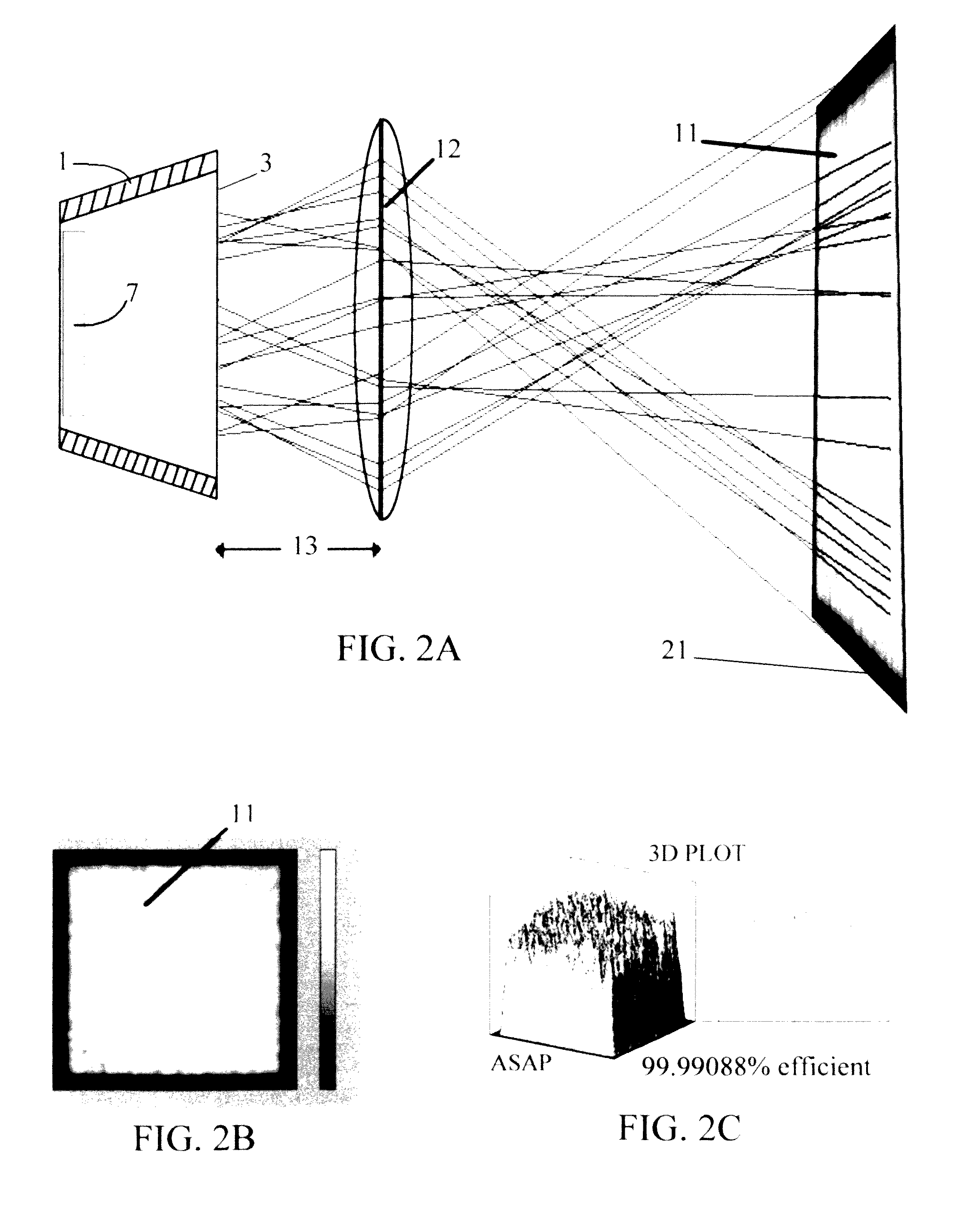
[0096]Reference will now be made in detail to the present preferred embodiment of the invention, examples of which are illustrated by the accompanying drawings. All of the computer generated information and prototyping was produced by the Breault ASAP Ray-Tracing Software program known throughout the optics industry for its accuracy and efficiency, and considered to be the best available. While the invention will be described in connection with a preferred embodiment, it will be understood that it is not intended to limit the invention to that embodiment.

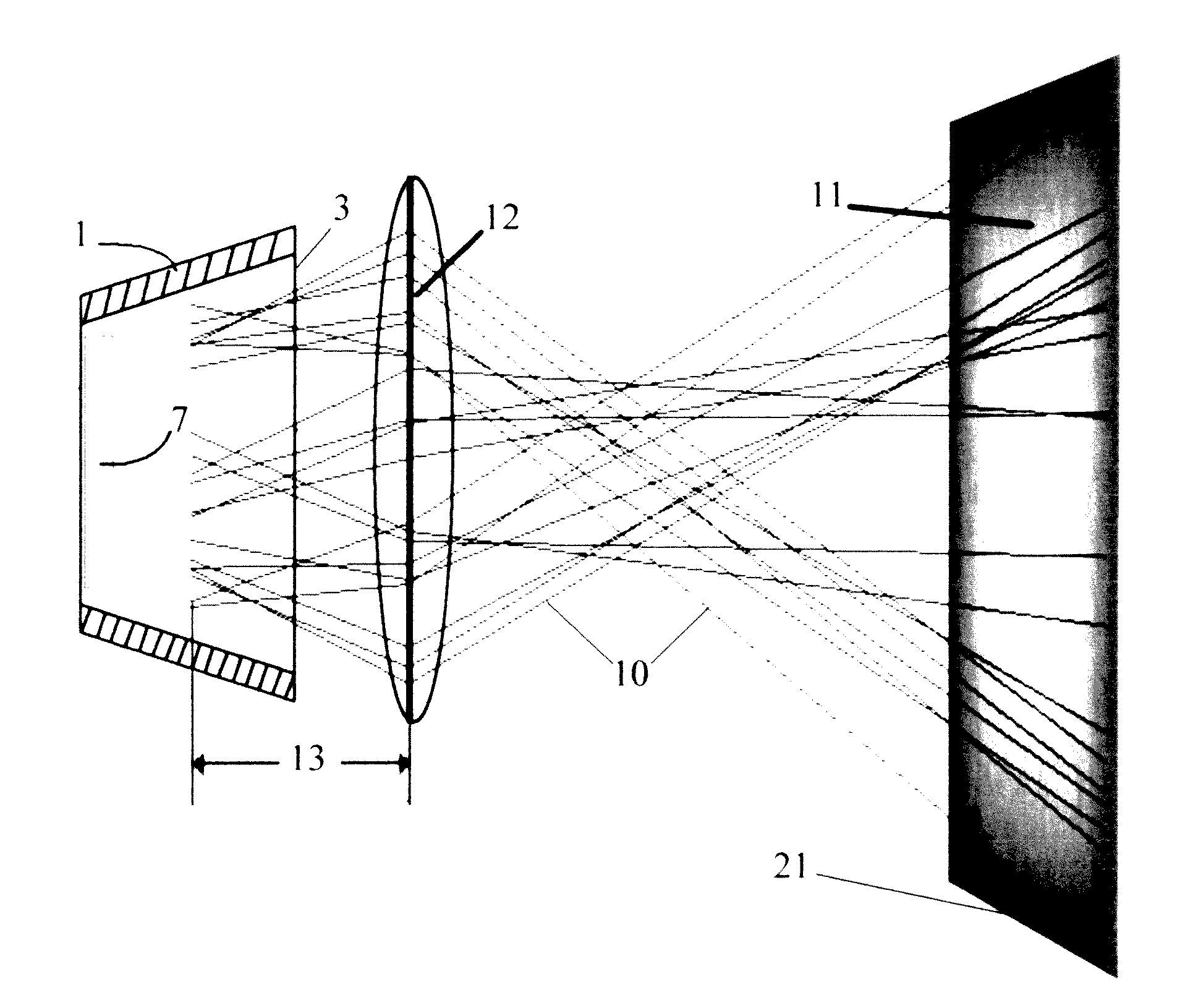
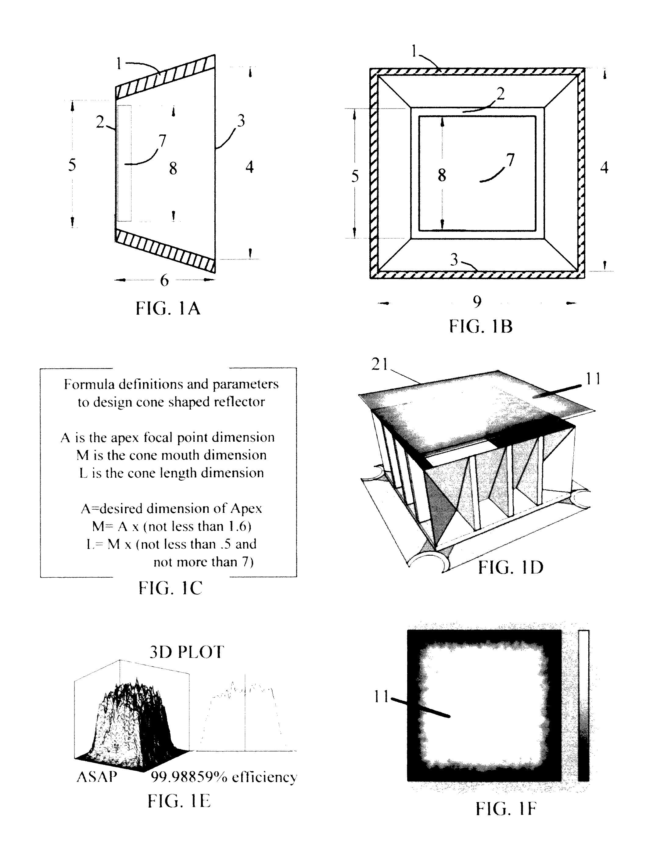
[0097]FIG. 1A is a schematic diagram with a side view, and FIG. 1B is a schematic diagram with a front view of a first embodiment of an improved primary optics illumination system in accordance with the invention, including a cone shaped reflector 1 with a square apex 2 and a square mouth 3 and an LED light source 7. The cone shaped reflector 1 is configured about a longitudinal axis wherein said reflector 1 has an apex 2 with a foc...


PUM


Abstract

An improved primary optics light projection system comprising a cone shaped reflector designed within specified mathematical parameters and a light source placed near the apex focal point cross sectional area of said reflector is disclosed for projecting a vortex of light rays with a precise shape and an even beam field containing a maximum number of light rays produced by a light source having a small or large diameter or cross section. A reflector near the base of the light source and perpendicular to the cone shaped reflector and one or more lens may be included to increase efficiency. The cone shaped reflector may be made in various cross sectional shapes providing means for using light sources with a square, rectangular, round, oval, or unconventional shape allowing the use of high efficiency light sources such as, but not limited to, light emitting diodes, often used in clusters of multiple LEDs.

Description

TECHNICAL FIELD[0001]The present invention is in the field of lamps and lighting fixtures and, more particularly, to an improved light projection system for efficiently redirecting substantially all of the light rays being emitted from a light source along a single projecting axis to form a precisely controllable high intensity beam of light providing maximum efficiency.BACKGROUND OF THE INVENTION[0002]Lamps and lighting fixtures have long been used to provide basic illumination and for specialty purposes such as, but not limited to, theatrical lighting, entertainment lighting, sports lighting, parking lot lighting, street lighting, and many other uses too numerous to list here. A majority of these lamps and lighting fixtures use devices such as various types of reflectors, various types of lenses, or a combination of these said devices in order to increase the efficiency and therefore increase usable light output of the light source being used.[0003]It is well known that in many in...

Claims


Application Information

Patent Timeline
Patent Type & Authority Patents(United States)
IPC IPC(8): F21V7/22F21V29/70F21V7/04
CPCF21V7/041F21V7/22F21V29/70F21Y2101/02F21V13/04F21Y2115/10
Inventor WIMBERLY, RANDAL L
Owner WIMBERLY RANDAL L
Why Eureka
Try Eureka