
Dredged soils long distance transport system using magnetic field and tornado and its control method thereof

a technology of dredged soil and long distance transportation, which is applied in the direction of packaging, bulk conveyors, non-mechanical conveyors, etc., can solve the problems of high installation cost, difficult repair/maintenance, and low economic benefit of dumping trucks, so as to promote efficient dredged soil transport and reduce resistance to flow

Active Publication Date: 2016-12-13
KOREA INST OF OCEAN SCI & TECH
View PDF12 Cites 0 Cited by
  • Summary
  • Abstract
  • Description
  • Claims
  • Application Information

AI Technical Summary

Benefits of technology

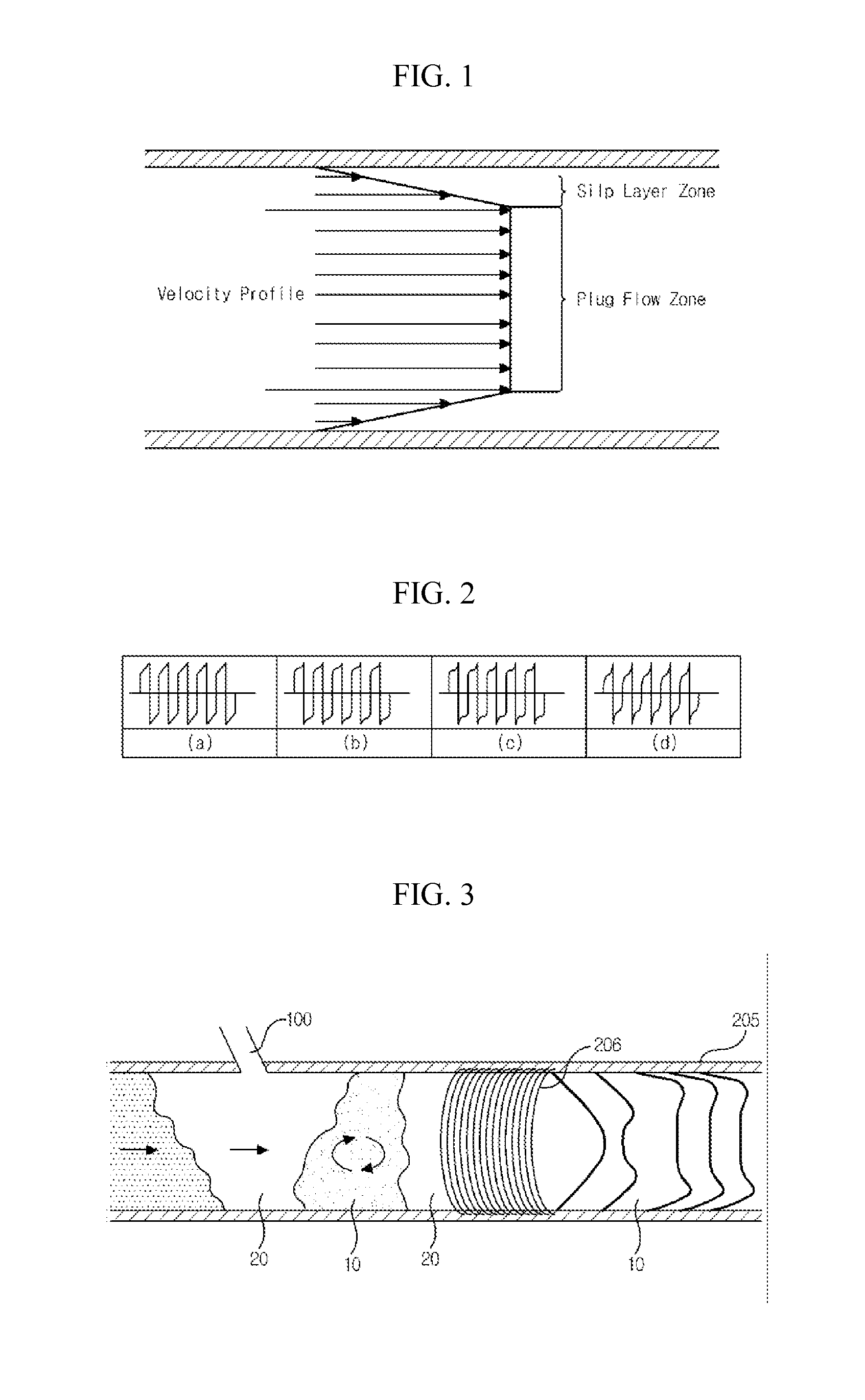
[0016]The present invention is provided to solve the various aforementioned problems and it is an object of the present invention to provide a long distance dredged soil transport system configured to promote an efficient dredged soil transport by decreasing resistance to flow of dredged soils inside pipelines by applying a electromagnetic field to the pipelines having a waveform catering to a field situation by grasping flow state during transport of dredged soils and generating plug flow, and a control method thereof.
[0037]The present invention can advantageously reduce transport costs by transporting dredged soil using a relatively small size of pump capacity when the dredged soil is transported to a long distance area.
[0038]Furthermore, the present invention can advantageously reduce damages of various transport equipment caused by long pipeline replacement period and pressure drop because the dredged soil can be transported under an environment where a transport pressure inside a pipeline is relatively low.
[0039]Still furthermore, the present invention can advantageously reduce an overall cost of a dredged soil transport system.

Problems solved by technology

Where, although the conveyor-using transport method is advantageous in that the conveyor-using transport method is adequate to a long-distance transport of dredged soils, the conveyor-using transport method is disadvantageous in that transport equipment and installation costs are expensive, and repair / maintenances are not easy.
Although the dump truck-using transport method is largely used, the dump truck-using transport method is not economically advantageous due to generation of noise and dusts when long transport distance is required.
Although it is general that the pipeline-using transport method is currently used, there may be lots of technical problems to be technically solved when dredged soils are transported long distance over 30 km.
Although the long distance transport of dredged soils take consideration of using relay pump methods using a booster line and transport methods using a siphon principle, these methods also entail problems of increasing dredging costs.
To be more specific, many stations are required for transport of dredged soils, that is, many high performance pumps are required at every place where fluids are pressurized and flow velocity is acquired, whereby installation costs of pumps and fuel costs for using the pumps increase geometrically.
Furthermore, material costs and installation costs of pipelines greatly increase because pressure inside the pipelines is high.
Currently used pipelines are cast iron pipes which are not efficient for high pressure.
Another disadvantage is that replacement periods are shortened due to damages to mechanical installation equipment including pipes and wear and tear of pipelines that require withstand of high pressure to thereby increase overall costs.
Still further disadvantage is that it is difficult to find a position of a clogged pipeline when a pipeline is clogged by dredged soils during long-distance transport of the dredged soils, and particularly, it is difficult to repair pipelines when the pipelines buried under ground are clogged and / or when the pipelines are holed.

Method used


Image

  • Dredged soils long distance transport system using magnetic field and tornado and its control method thereof
  • Dredged soils long distance transport system using magnetic field and tornado and its control method thereof
  • Dredged soils long distance transport system using magnetic field and tornado and its control method thereof

Examples


Embodiment Construction

[0049]Hereinafter, exemplary embodiments of the present disclosure will be described in detail with reference to the accompanying drawings. In the drawings, sizes or shapes of constituent elements may be exaggerated for clarity and convenience.

[0050]In describing the present disclosure, detailed descriptions of constructions or processes known in the art may be omitted to avoid obscuring appreciation of the invention by a person of ordinary skill in the art with unnecessary detail regarding such known constructions and functions.

[0051]Accordingly, particular terms may be defined to describe the disclosure in the best mode as known by the inventors. Accordingly, the meaning of specific terms or words used in the specification and the claims should not be limited to the literal or commonly employed sense, but should be construed in accordance with the spirit and scope of the disclosure. The definitions of these terms therefore may be determined based on the contents throughout the spe...


PUM


Abstract

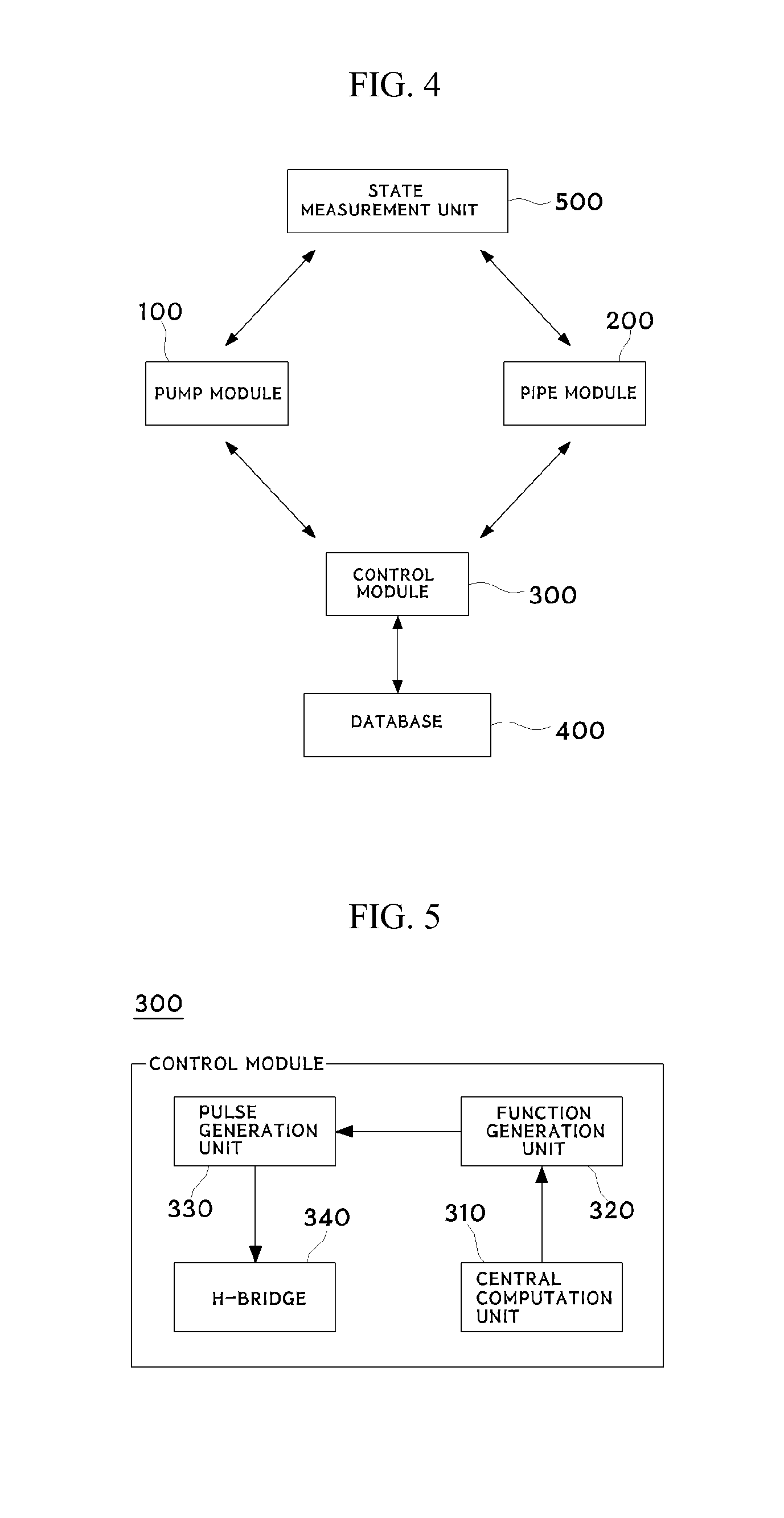
A long distance dredged soil transport system includes a pump module including a pump for generating a compressed air and a plug flow flowing by dividing an inner state of a pipeline to a gaseous unit and a liquefied unit by introducing the generated compressed air into the pipeline by being interlinked to one lateral surface of the pipeline, a pipe module wound with a coil to apply an electromagnetic wave to the liquefied unit and including a plurality of pipelines, database stored with flow information on flow velocity and flow form in response to physical properties of liquefied unit, and a control module communicating with the pipe module, the pump module and the database and applying, to the coil, a waveform of a current matching to a flow waveform of the liquefied unit transported inside the pipeline, and a control method thereof.

Description

CROSS REFERENCE TO RELATED APPLICATIONS AND CLAIM OF PRIORITY[0001]This patent application is a National Phase application under 35 U.S.C. §371 of International Application No. PCT / KR2014 / 004779, filed May 29, 2014, which claims priority to Korean Patent Application No. 10-2014-0011285, filed Jan. 29, 2014, entire contents of which are incorporated herein by reference.BACKGROUND[0002]Technical Field[0003]The present invention relates to a long distance dredged soil transport system using magnetic field and tornado eddy current technique, and a control method thereof, and more particularly to a long distance dredged soil transport system configured to increase dredged soil transport efficient by decreasing dredged soil transport pressure using electromagnetic field by generating plug flow, and a control method thereof.[0004]Background Invention[0005]Dredged soils are soils deposited on rivers or oceans for obtaining soils and sands necessary for construction sites, and although river...

Claims


Application Information

Patent Timeline
Patent Type & Authority Patents(United States)
IPC IPC(8): B65G54/02B65G53/30B65G53/52
CPCB65G54/02B65G53/30B65G53/52B65G53/525B65G2201/045B65G2207/14B65G53/10B65G53/526F17D1/00
Inventor YOON, GIL-LIMKIM, YUSEUNG
Owner KOREA INST OF OCEAN SCI & TECH
Learn More