Electrolyzing cell for generating hydrogen and oxygen and method of use

a hydrogen and oxygen and electrolysis cell technology, applied in the field of electrolysis cells, can solve the problems of generating voltage loss, cell thermal runaway, and need for costly electronics to monitor, and achieve the effects of enhancing output, reducing voltage loss, and reducing voltage loss

Active Publication Date: 2016-12-13
GLOBAL HYDROGEN TECH +2
View PDF25 Cites 0 Cited by
  • Summary
  • Abstract
  • Description
  • Claims
  • Application Information

AI Technical Summary

Benefits of technology

[0008]The electrolytic cell of the present invention is used to electrolyze water and produce hydrogen and oxygen. The cell arrangement is designed to allow rapid flow of electrolyte through the cell to enhance output and to create the designed “flow barrier” to limit voltage loss at the plate edges where the electrolyte flows in and out, without the need of mechanical barriers or membranes. The cell housing is formed of nonconductive and adapted to enclose the positive and neutral electrode plates of the cell, eliminating most voltage leak paths and forming a protective barrier to the potential of shorting that is common on dry cell designs. The housing may contain any shape known in the art as useful as an electrolytic cell. In some variations, the housing includes first and second transverse walls, each having an opening edge, a base edge, and two longitudinal edges. A third and fourth longitudinal walls, each having an opening edge, a base edge, and two transverse edges, connect to the transverse walls or are otherwise in communication with the first and second transverse walls via the transverse edges. A base having an interstitial face and exterior face, is connected or otherwise in communication with the base edge of the first and second transverse walls and third and fourth longitudinal walls, forming an interstitial space. However, other useful forms may be used, such as a circular electrolysis cell. In such a variation, the first through forth walls are a continuous cylindrical shape. The housing includes at least one positive terminal base aperture on the interstitial face of the base.
[0011]A negative plate, formed of electroconductive material, having substantially the same dimensions as the housing, is disposed on the opening edge of the housing. The present electrolyzing cell has one potential leak path as opposed to 14 in the prior art designs, such as Henes (U.S. Pat. No. 4,425,215), where the negative plate attaches to the cell casing. Sealers, such as an o-ring and / or sealant eliminate leakage. In some variations, a groove is disposed on the opening edge of the housing and adapted to accept an o-ring, rubber gasket, silicon sealant, such as Dow Corning® EA-6052, EA-6054, 90-006 Aerospace Sealant, 93-006 Aerospace Sealant, 94-031 Fluorosilicone Channel Sealant, HM-2500 Assembly Sealant, 700 Industrial Grade Silicone Sealant; epoxy sealants, such as those manufactured by Dow Corning® and Permatex; urethane sealants, such as Bostik® 2100 SPS Urethane Sealant, Sika Sikaflex-221 Non-Sag Polyurethane Sealant, Sika Sikaflex-221 Non-Sag Polyurethane Sealant, 3M 540 Polyurethane Adhesive / Sealant, 3M 4000 UV Marine Adhesive / Sealant 3M 550 and 551 Polyurethane Adhesive / Sealant, and sealants manufactured by Dow Corning; polyisobutylene (PIB) sealants, such as H. B. Fuller Window GmbH PIB-969S and sealants manufactured by Dow Corning; acrylic sealants, such as those manufactured by Dow Corning, polysulfide sealant, such as PRC Rapid Seal 650 Polysulfide Sealant, which interacts with the negative plate to seal the cell. Some variations of the cell include a plurality of case bolt apertures disposed on the opening edge of the housing, where the case bolt apertures extend through the housing or extend through a portion of the housing and a plurality of plate mounting holes are disposed on the negative plate, which correspond to the case bolt apertures. Alternatively, the negative plate is affixed to the housing a sealant glue, such as those described above. Where case bolt apertures extend through a portion of the housing, and not fully through the housing, the plurality of case bolt apertures are threaded such that the threaded apertures are adapted to accept a case bolt. A plurality of plate mounting holes are optionally disposed on a face of the negative plate, and correspond to the case bolt apertures, allowing bolts to fix the negative plate to the housing. In some variations, the plate mounting holes are countersunk. The electrolysis cell may also include a sealant disposed on the opening edge of the housing, wherein the sealant is silicone sealant, epoxy sealant, urethane sealant, polyisobutylene sealant, or acrylic sealant, such as those listed above.
[0018]The electrolysis cell may be formed of different dimensions, based on the output needs and application. It would be known to one skilled in the art how to scale the size of the cell for specific application. The cell not “stackable” as seen in conventional cells, as the stack is set and enclosed by the dividers which provide exact cell spacing and seal the plate edges eliminating areas of voltage loss common to dry cells with flow ports drilled in their electrodes. However, the cell may be wired in parallel or in series, or can be plumbed for electrolyte flow in parallel or series to suit system needs.

Problems solved by technology

However, these holes also create voltage loss.
However, these cells require periodic checks to maintain water level or drip-feed systems to replenish the cells.
These cells also exhibit thermal runaway and / or the need for costly electronics to monitor and modulate current for prevention of overloads.
The small ports created for the flow into each cell have the liability of becoming plugged or restricted by contaminants as well as electrolyte solids.
They also create issues with leakage of electrolyte from the external manifolds.
This results in reduced efficiency and increased maintenance requirements.
These cells have large potential voltage leakage at each every plate, due in part to the ports cut into each plate for the bolts and flow paths when plates are sandwiched together.
These ports create areas of voltage leakage between anode and cathode, with the edges of the holes leaking voltage around their entire circumference.
These cells have efficiency limitations and they produce steam in addition to the gas created by electrolysis.
However, stacked cells using such a design suffer from a final assembly that is very bulky, limiting its potential applications due to space constraints, such as in modern vehicles, where engine space is very limited.
Further, the design results in substantial labor requirements during assembly, as different plates need to be arranged and isolated, and then the entire assembly must be bolted together.
However, the cell requires mechanical isolation, with an extremely bulky design.
However, most electrolyzers in the art display significant voltage loss, due to ports provided in the various electrode plates.

Method used


Image

  • Electrolyzing cell for generating hydrogen and oxygen and method of use
  • Electrolyzing cell for generating hydrogen and oxygen and method of use
  • Electrolyzing cell for generating hydrogen and oxygen and method of use

Examples


example

[0043

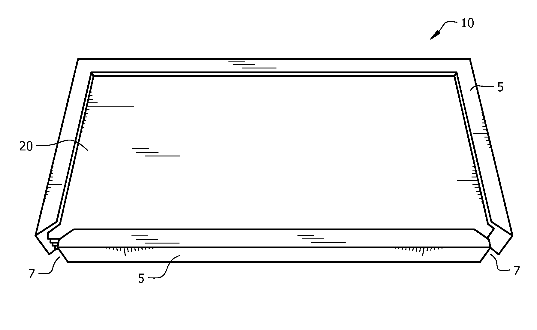
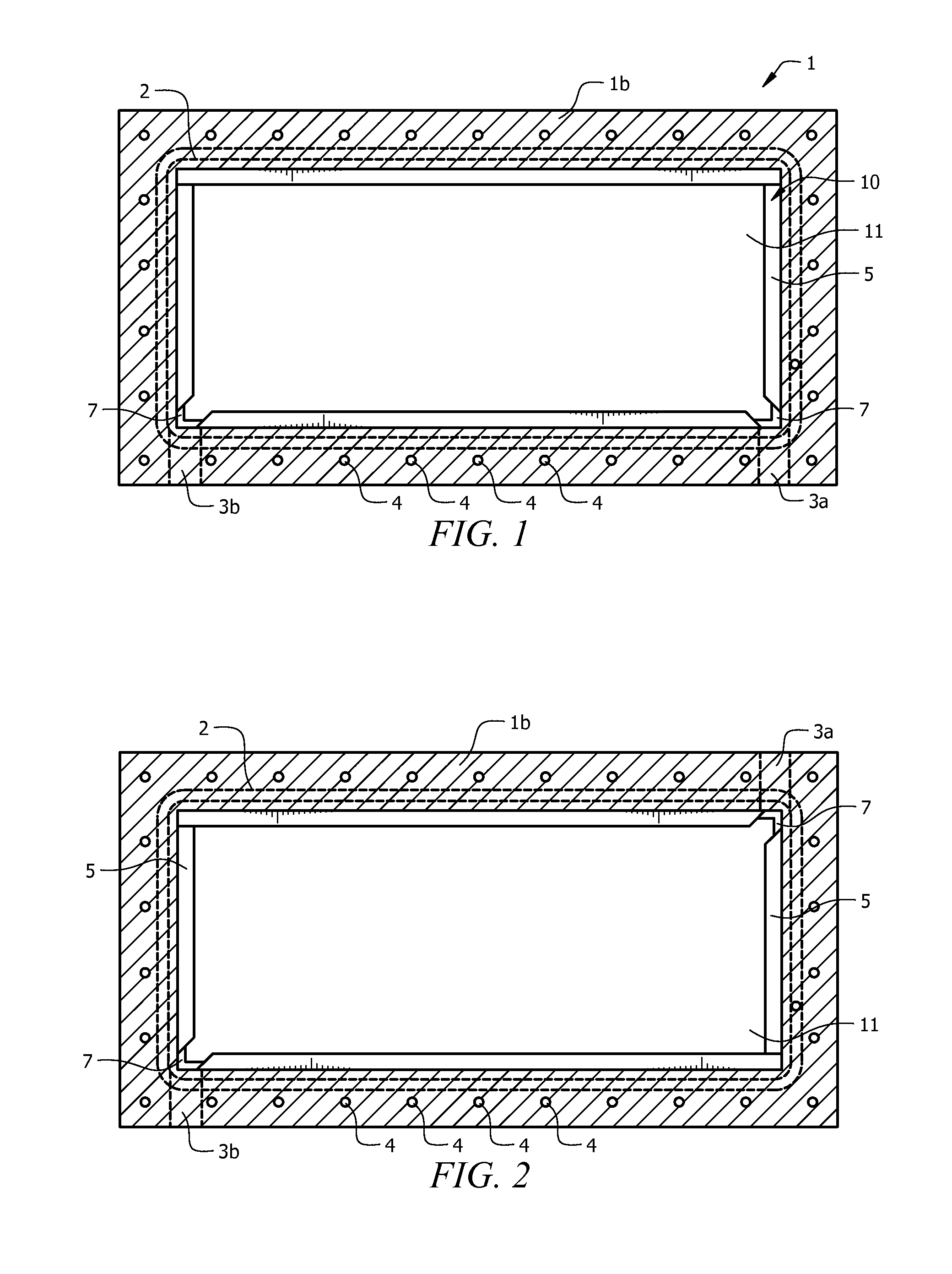
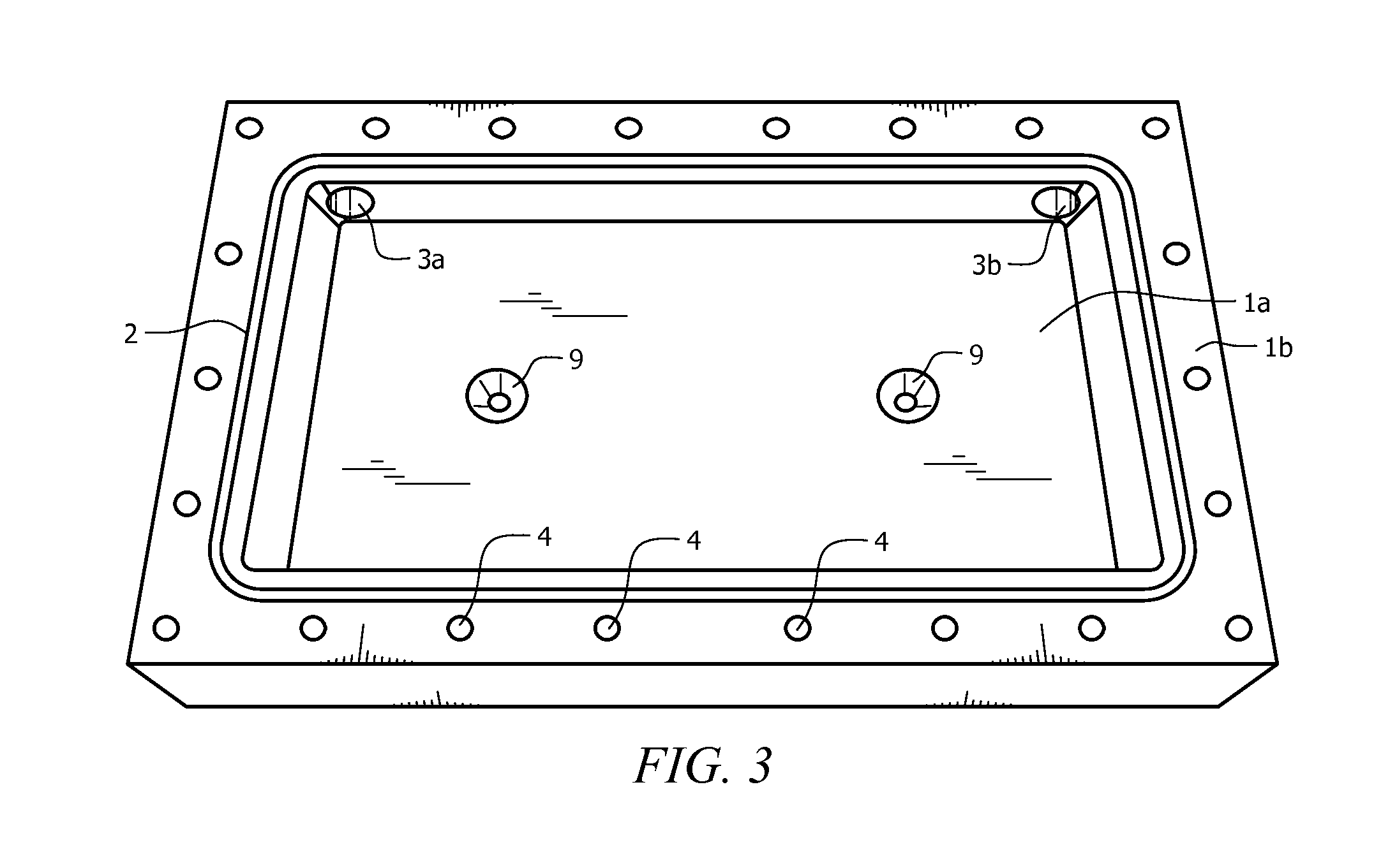
[0044]The electrolyzer cell comprises cassette 10 and positive plate 30 enclosed in housing 1, as seen in FIG. 1. Housing 1 is made from known non-conductive materials, such as acrylic, acetal, delrin, or plastic, and provides for pressure retention and rigidity to positive plate, thereby maintaining tolerances. Housing 1 includes an interstitial space adapted to accept cassette 10. Preferably, cassette 10 fits tightly into the interstitial space. The closed base of housing 1 forms positive electrode base 1a, with at least one opening provided in positive electrode base 1a, as seen in FIG. 3. The open, upper face of housing 1 forms negative electrode face 1b. A groove runs outside the interstitial space on negative electrode face 1b, forming case o-ring channel 2, which fits case o-ring 50, seen in FIG. 4. A plurality of electrolyte flow apertures 3a and 3b are providing running from the outside edge of housing 1 to the interstitial space, seen in FIG. 1. Electrolyte flow fitti...


PUM

PropertyMeasurementUnit
voltageaaaaaaaaaa
temperatureaaaaaaaaaa
electroconductiveaaaaaaaaaa

Abstract

An electrolytic cell used to electrolyze water and produce hydrogen and oxygen. The cell comprises nonconductive dividers, sandwiching neutral electrodes and designed for rapid flow of electrolyte through the cell to limit voltage loss. A positive electrode plate is disposed in the interstitial space of a nonconductive housing, adjacent to the neutral electrodes. At least one terminal connects to the positive electrode. A negative electrode seals the cell and is sealed with an o-ring. The cell may be mounted to a vehicle or other system using a mounting tab, which optionally also functions as a ground. The cell may use gravitic circulation or a circulating pump to cycle electrolyte. The electrolysis cell may be formed of different dimensions, based on the output needs and application, and may be wired in parallel or in series to suit system needs.

Description

CROSS-REFERENCE TO RELATED APPLICATIONS[0001]This application is a continuation of and claims priority to International Patent Application No. PCT / US2011 / 057296, entitled: “Electrolyzing Cell for Generating Hydrogen and Oxygen and Method of Use,” filed on Oct. 21, 2011, the contents of which are herein incorporated by reference.FIELD OF INVENTION[0002]This invention relates to an electrolyzing cell. More specifically, the invention is an electrolyzing cell having solid electrode plates providing simple method for controlling voltage loss without impeding electrolyte flow potential.BACKGROUND OF THE INVENTION[0003]Electrolysis cells consist of an anode, a cathode and plates in between the anode and cathode that are not directly connected to ground or power but are active by conductivity of the electrolyte. These are called “neutral plates” or bipolar plates. Some cells have holes in the anode and cathode as well as the neutral plates for allowing flow of electrolyte. However, these h...

Claims


Application Information

Patent Timeline
Patent Type & Authority Patents(United States)
IPC IPC(8): C25B9/02C25B9/06C25B1/08C25B9/17
CPCC25B9/02C25B1/08C25B9/063Y02E60/366Y02E60/36C25B1/04C25B9/73C25B9/63C25B11/036
Inventor GRIMM, HELMUTH E.
Owner GLOBAL HYDROGEN TECH
Why Eureka
Try Eureka