Lighting devices that comprise one or more solid state light emitters

a technology of light emitting diodes and lighting devices, which is applied in the manufacture of electrode systems, electric discharge tubes/lamps, lighting and heating apparatuses, etc., can solve the problems of incandescent light bulbs that are very energy-inefficient light sources, light emitting diodes are still less efficient than solid-state light emitters, and incandescent light bulbs have relatively short lifetimes. , to achieve the effect of reducing equipment cost, prolonging the life of other components o

Active Publication Date: 2016-12-13
CREELED INC
View PDF145 Cites 6 Cited by
  • Summary
  • Abstract
  • Description
  • Claims
  • Application Information

AI Technical Summary

Benefits of technology

[0024]As noted above, one very attractive quality of solid state lighting is its efficiency and hence its low operating cost. A quality of solid state lighting that has hindered its use, however, is its equipment cost. One way to make solid state lighting more attractive would be to extend the already superior useful life of at least some of the components of lighting devices that employ solid state lighting, whereby the equipment cost over time is even further reduced in comparison with other lighting options.
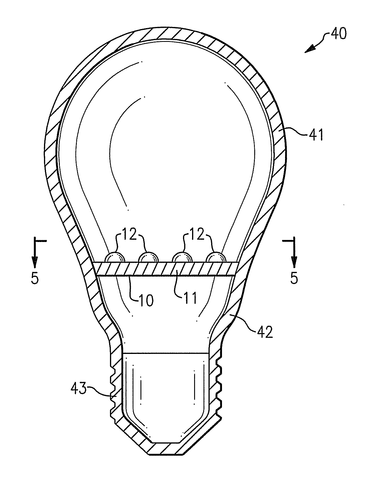
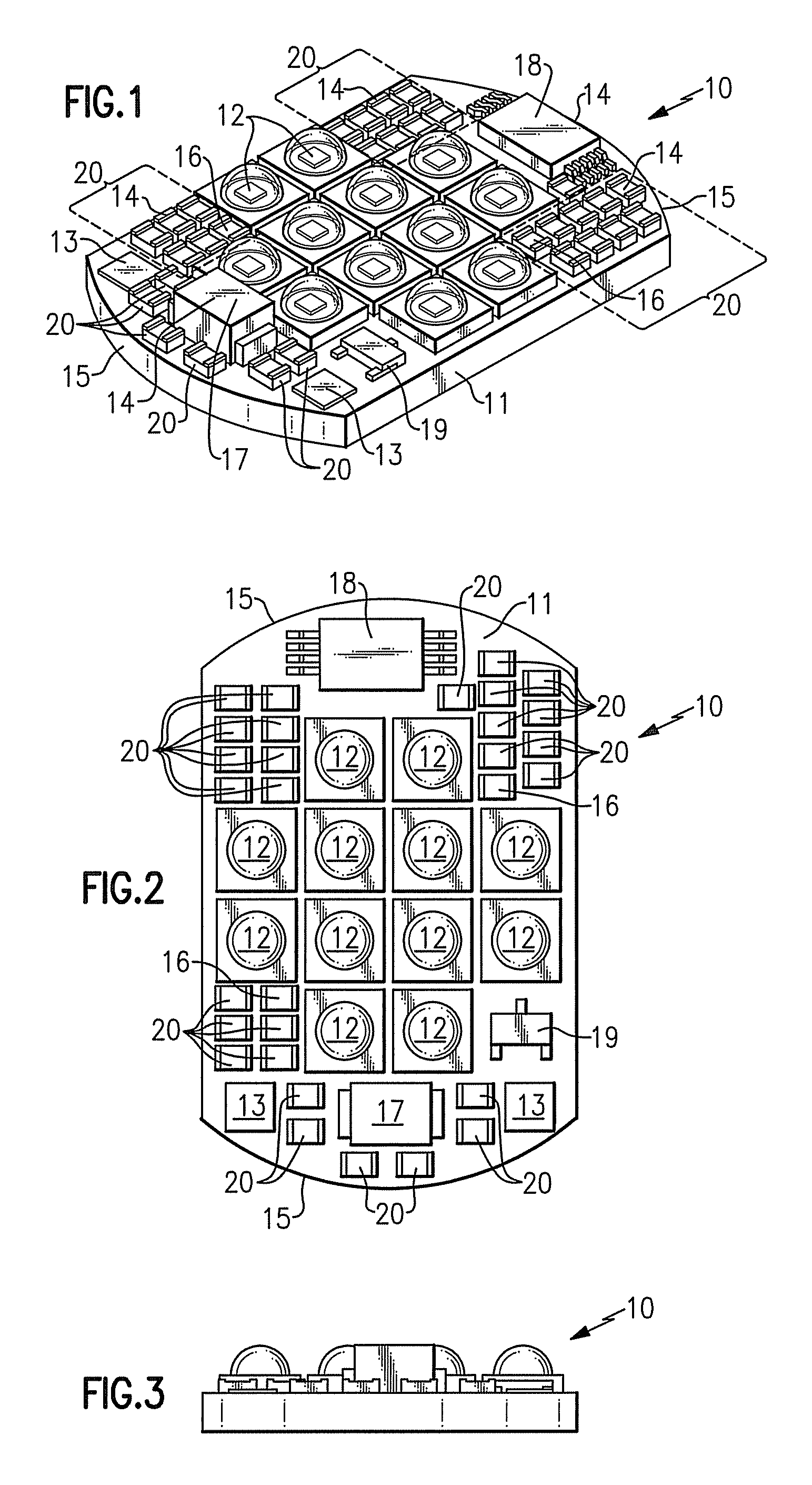
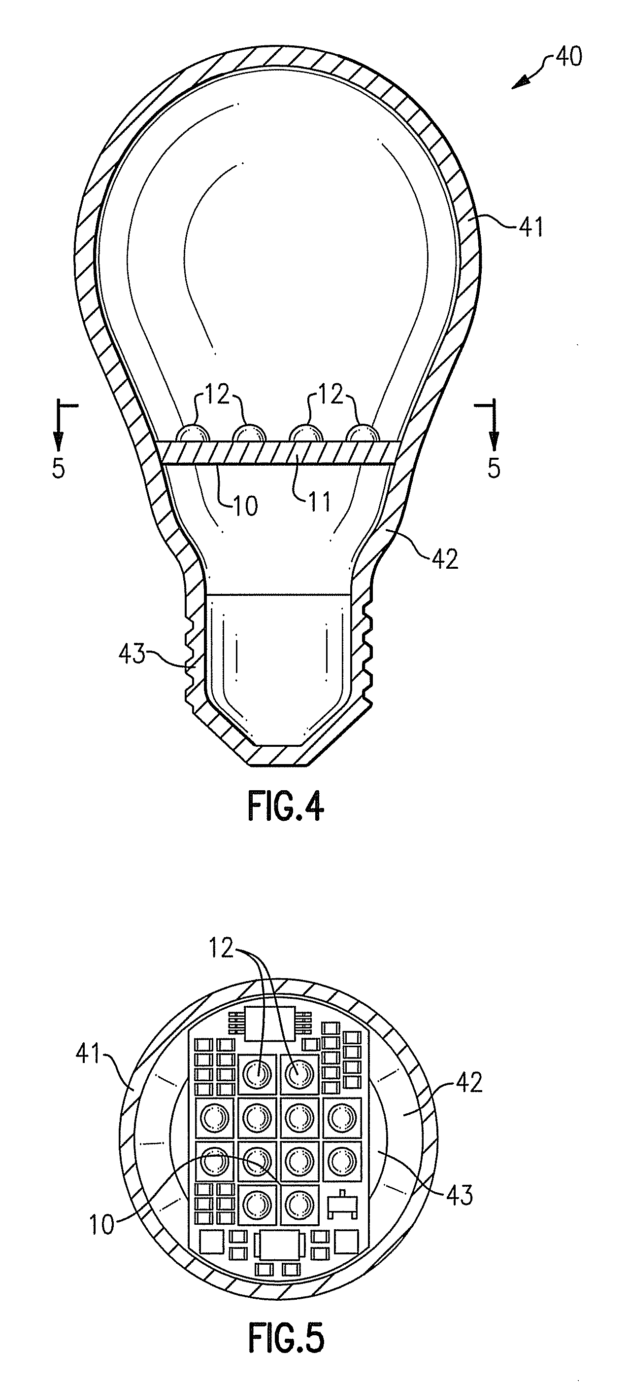
[0027]In accordance with another aspect of the present inventive subject matter, there is provided a lighting device that comprises a removable light engine module, e.g., that comprises a support member on which at least one solid state light emitter is mounted. With such a lighting device, it is possible to periodically replace the support member and the one or more solid state light emitters mounted thereon, according to a predetermined schedule, whenever desired or whenever deemed necessary. In such a way, the lifetime of the other components of the lighting device can be extended, and / or the lighting device can be operated at higher temperature (i.e., to generate more light) than would otherwise be possible, and / or different color output can be achieved by swapping out one or more support members (along with the solid state light emitter or solid state light emitters mounted thereon).
[0028]For example, in satisfying a given lighting requirement (e.g., overall brightness in a particular room, e.g., a dining area in a restaurant), equipment cost can be reduced by using fewer lighting devices and supplying higher current to the at least one solid state light emitter to make up for the fewer number of lighting devices. In such a case, it is recognized that the higher operating temperatures generated by operating the at least one solid state light emitter at higher current may cause the solid state light emitters to degrade more rapidly (due primarily to degradation of encapsulant), but that the effects of such degradation can be addressed by replacing the light engine module (including the one or more solid state light emitters that is / are part of that module) at the onset of degradation (or at any other stage of degradation).
[0029]Alternatively or additionally, equipment cost can be reduced (or further reduced) by eliminating one or more heat sink elements that would otherwise be provided in order for the operating temperature of the at least one solid state light emitter to be held to a level at which degradation of the at least one solid state light emitter is kept below a threshold level ordinarily deemed to be unacceptable, recognizing that the effects of more rapid degradation of the at least one solid state light emitter resulting from such higher operating temperatures can be addressed by replacing the light engine module (or one or more of plural light engine modules), including the one or more solid state light emitters that is / are part of that module, at the onset of degradation (or at any other stage of degradation).

Problems solved by technology

It is well known that incandescent light bulbs are very energy-inefficient light sources—about ninety percent of the electricity they consume is released as heat rather than light.
Fluorescent light bulbs are more efficient than incandescent light bulbs (by a factor of about 10) but are still less efficient than solid state light emitters, such as light emitting diodes.
In addition, as compared to the normal lifetimes of solid state light emitters, e.g., light emitting diodes, incandescent light bulbs have relatively short lifetimes, i.e., typically about 750-1000 hours.
Fluorescent bulbs generally have lifetimes (e.g., 10,000-20,000 hours) that are longer than those of incandescent lights, but they typically provide less favorable color reproduction.
The impact of the need to replace light emitters is particularly pronounced where access is difficult (e.g., vaulted ceilings, bridges, high buildings, highway tunnels) and / or where change-out costs are extremely high.
There are a number of challenges presented with using solid state light emitters in lighting devices.
One such challenge results from the fact that the emission spectrum of any particular light emitting diode is typically concentrated around a single wavelength (as dictated by the light emitting diode's composition and structure), which is desirable for some applications, but not desirable for others, (e.g., for providing general illumination, such an emission spectrum generally does not provide light that appears white, and / or provides a very low CRI).
As a result, in many of such devices, one challenge that necessitates the inclusion of additional components is that there may be a desire to provide additional circuitry that can adjust the current supplied to respective solid state light emitters (and / or other light emitters) in order to maintain the balance of color output among the light emitters that emit light of different colors in order to achieve the desired color output.
Another such challenge is that there may be a desire to mix the light of different colors emitted from the different solid state light emitters by providing additional structure to assist in such mixing.
Another challenge presented in making a lighting device with light emitting diodes, that often necessitates the inclusion of additional components, is that the performance of many solid state light emitters may be reduced when they are subjected to elevated temperatures.
Another challenge presented in making a lighting device with light emitting diodes, that often necessitates the inclusion of additional components, arises from the relatively high light output from a relatively small area provided by solid state emitters.
Such a concentration of light output may present challenges in providing solid state lighting systems for general illumination in that, in general, a large difference in brightness in a small area may be perceived as glare and may be distracting to occupants.
Another challenge presented in making a lighting device with light emitting diodes, that often necessitates the inclusion of additional components, is that light emitting diodes are typically operated most effectively on low voltage DC current, while line voltage is typically much higher voltage AC current.

Method used


Image

  • Lighting devices that comprise one or more solid state light emitters
  • Lighting devices that comprise one or more solid state light emitters
  • Lighting devices that comprise one or more solid state light emitters

Examples


Embodiment Construction

[0062]The present inventive subject matter now will be described more fully hereinafter with reference to the accompanying drawings, in which embodiments of the inventive subject matter are shown. However, this inventive subject matter should not be construed as being limited to the embodiments set forth herein. Rather, these embodiments are provided so that this disclosure will be thorough and complete, and will fully convey the scope of the inventive subject matter to those skilled in the art. Like numbers refer to like elements throughout. As used herein the term “and / or” includes any and all combinations of one or more of the associated listed items.

[0063]The terminology used herein is for the purpose of describing particular embodiments only and is not intended to be limiting of the inventive subject matter. As used herein, the singular forms “a”, “an” and “the” are intended to include the plural forms as well, unless the context clearly indicates otherwise. It will be further ...


PUM


Abstract

Light engine modules comprise a support member and a solid state light emitter, in which (1) the emitter is mounted on the support member, (2) a region of the support member has a surface with a curved cross-section, (3) the emitter and a compensation circuit are mounted on the support member, (4) an electrical contact element extends to at least two surfaces of the support member, and / or (5) a substantial entirety of the module is located on one side of a plane and the emitter emits light into another side of the plane. Also, a module comprising means for supporting a light emitter and a light emitter. Also, a lighting device comprising a housing member and a light emitter mounted on a removable support member. Also, a lighting device comprising a module mounted in a lighting device element. Also, a method comprising mounting a module to a lighting device element.

Description

FIELD OF THE INVENTIVE SUBJECT MATTER[0001]The present inventive subject matter is directed to lighting devices that comprise one or more solid state light emitters, e.g., one or more light emitting diodes.BACKGROUND[0002]There is an ongoing effort to develop systems that are more energy-efficient. A large proportion (some estimates are as high as twenty-five percent) of the electricity generated in the United States each year goes to lighting, a large portion of which is general illumination (e.g., downlights, flood lights, spotlights and other general residential or commercial illumination products). Accordingly, there is an ongoing need to provide lighting that is more energy-efficient.[0003]Solid state light emitters (e.g., light emitting diodes) are receiving much attention due to their energy efficiency. It is well known that incandescent light bulbs are very energy-inefficient light sources—about ninety percent of the electricity they consume is released as heat rather than l...

Claims


Application Information

Patent Timeline
Patent Type & Authority Patents(United States)
IPC IPC(8): H01J5/48F21V3/00F21V23/00F21V19/00F21V19/04F21Y101/00F21Y105/00
CPCF21V3/00F21K9/232F21V19/003F21V23/005F21Y2107/40F21Y2115/10F21Y2101/00F21Y2105/00F21V19/04F21V23/006F21K9/238
Inventor VAN DE VEN, ANTONY PAUL
Owner CREELED INC
Why Eureka
Try Eureka