Signal transmission connector

a technology of transmission connector and terminal molding, which is applied in the direction of connection, electrical apparatus, coupling device connection, etc., can solve the problems of substantial modification of terminal molding and substantial increase in cost, and achieve the effect of simple structure, cost reduction and easy manufacturing

Active Publication Date: 2016-12-13
NEXTRONICS ENG CORP
View PDF1 Cites 5 Cited by
  • Summary
  • Abstract
  • Description
  • Claims
  • Application Information

AI Technical Summary

Benefits of technology

[0009]The object of the instant disclosure is to provide an adjustable impedance of the signal transmission connector terminal structure without modification thereof while providing simple structure, the easy of manufacturing, and cost reduction.
[0015]The most preferred widths of the first and the second terminals range from 0.36 to 0.42 mm, the dielectric constant of the insulating body ranges from 3 to 3.4, and the dielectric constant of the rear cover ranges from 3.5 to 3.8. The rear casing and the body have different dielectric constants. The rear casing can be the most preferably matched such that differential signal of the connector has the most preferred impedance, crosstalk is reduced, and in turn increases data transfer rate. Furthermore, the terminal structures of the instant disclosure need not vary to provide adjustable impedance. The terminals have simple structures, provide ease of manufacturing, and reduce production cost.
[0018]Impedance matching is maintained by adjusting the shape of the plastic slots, dielectric constants and the preferred terminal widths to modify corresponding inductance and capacitance, such that stability of signal transmission at the terminals is maintained. The pitch further emphasizes the control of impedance.

Problems solved by technology

If the gap between terminals of the differential coupling connector is modified, the terminal structures are also affected such that substantial modifications to the terminal moldings are required, and in turn costs are substantially increased.

Method used


Image

  • Signal transmission connector
  • Signal transmission connector
  • Signal transmission connector

Examples


Embodiment Construction

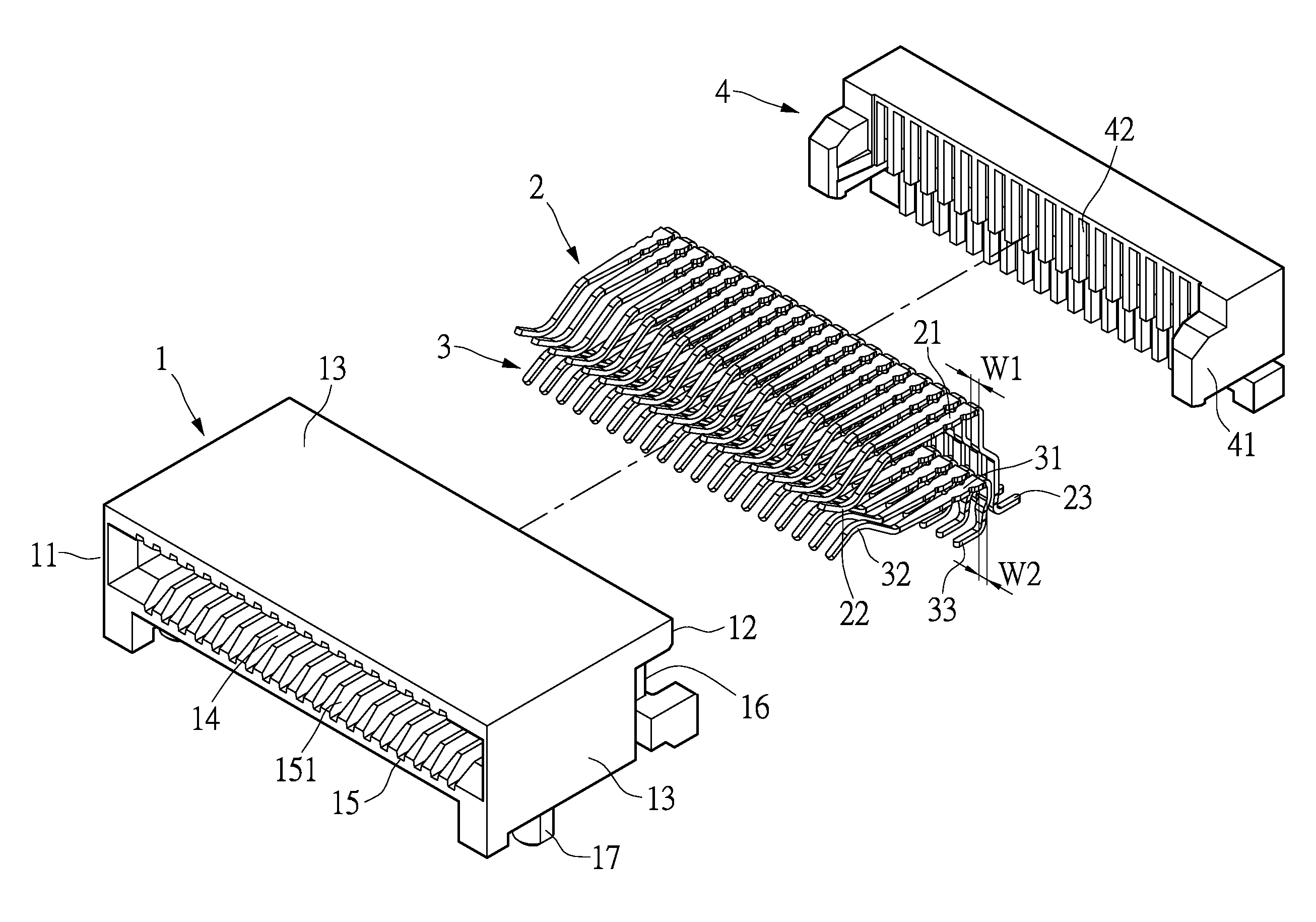
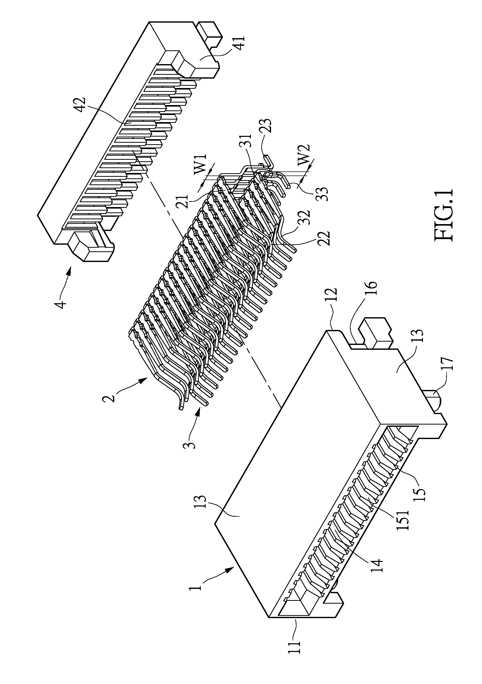
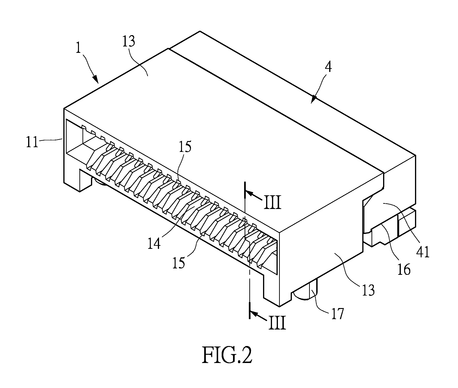
[0026]Please refer to FIGS. 1 to 3. The instant disclosure provides a signal transmission connector, specifically, a small detachable module connector compatible with small form-factor pluggable standards. The signal transmission connector includes an insulating body 1 (the body 1), a plurality of first terminals 2, a plurality of second terminals 3, and a rear casing 4.

[0027]The body 1 is made of insulating materials (such as plastics). The body 1 has a first end 11 and the second end 12 opposite to the first end 11. The first end 11 and the second end 12 have four sidewalls 13 connected therebetween. The four sidewalls 13 are respectively defined as the top side, the bottom side, the left side, and the right side of the insulating body 1. Top, bottom, left, and right are terms serving only as reference orientations in the embodiments of the instant disclosure, but do not limit the scope of the instant disclosure to the orientation of the sidewalls provided by the examples herein. ...


PUM


Abstract

A signal transmission connector includes an insulating body, a plurality of first terminals, a plurality of second terminals, and a rear casing. The insulating body has a dielectric constant of about 3 to 3.4. The first and second terminals are disposed on the insulating body. The first and second terminals have widths of about 0.36 to 0.42 mm. The rear casing is assembled at the second end of the insulating body. The rear casing envelops the first and the second terminals. The rear casing has a dielectric constant of about 3.5 to 3.8. The connector provides adjustable impedance without modifications to the terminal structures and also reduces cost.

Description

CROSS-REFERENCE TO RELATED APPLICATIONS[0001]This application is a Continuation-in-Part of application Ser. No. 14 / 158,810 filed Jan. 18, 2014, now pending, and entitled Signal Transmission Connector.BACKGROUND OF THE INVENTION[0002]1. Field of the Invention[0003]The instant disclosure relates to a signal transmission connector; in particular, to a signal transmission connector for small form-factor pluggables (SFP).[0004]2. Description of Related Art[0005]Conventional transceiver modules typically apply to connect circuit board for communication lines and other electrical modules and equipment. Various industrial standards define computer and external communication equipment such as modems, network interfaces or other connector types having different transceiver module interfaces. Gigabit interface converter (GBIC) is a computer with Ethernet, fiber optic channels, or other data transceiver modules capable of data communication.[0006]In order to improve port density between network...

Claims


Application Information

Patent Timeline
Patent Type & Authority Patents(United States)
IPC IPC(8): H01R13/6477H01R12/72H01R13/506
CPCH01R13/6477H01R12/721H01R13/506
Inventor SU, HOU-ANHSU, HUNG-WEIYANG, CHANG-FAWANG, HUAI-SHENG
Owner NEXTRONICS ENG CORP
Why Eureka
Try Eureka