
Spark plug

a technology of spark plugs and plugs, which is applied in the manufacture of spark plugs, spark plugs, electrical equipment, etc., can solve the problems of increased risk of center electrode breakage, and the ignition performance of spark plugs in internal combustion engines deteriorates with the decrease of the axial length of the part constituted, so as to achieve the effect of minimizing deflection

Active Publication Date: 2016-12-20
NGK SPARK PLUG CO LTD
View PDF22 Cites 0 Cited by
  • Summary
  • Abstract
  • Description
  • Claims
  • Application Information

AI Technical Summary

Benefits of technology

The patent text describes a configuration that ensures good ignition performance and durability of the center electrode in a spark plug. It also prevents excessive wear of the noble metal tip and improves breakage resistance of the center electrode in cases where the diameter of the large-diameter portion is small. Additionally, the text suggests that minimizing deflection between the small-diameter portion and the connection portion can be achieved by satisfying certain conditions.

Problems solved by technology

There is however a problem that the risk of breakage of the center electrode increases due to increases in vibration and combustion pressure when the compression ratio of the internal combustion engine becomes high.
In particular, the vibration of the center electrode is large so that there is a higher risk of breakage of the center electrode in the case where the large-diameter portion of the center electrode is relatively small in diameter.
However, the ignition performance of the spark plug in the internal combustion engine deteriorates with decrease in the axial length of the part constituted by the small-diameter portion and the noble metal tip.
In this way, there is a problem of achieving compatibility between improvement of the ignition performance of the spark plug and improvement of the breakage resistance of the center electrode.

Method used


Image

  • Spark plug
  • Spark plug
  • Spark plug

Examples


embodiment

A. Embodiment

A-1. Structure of Spark Plug

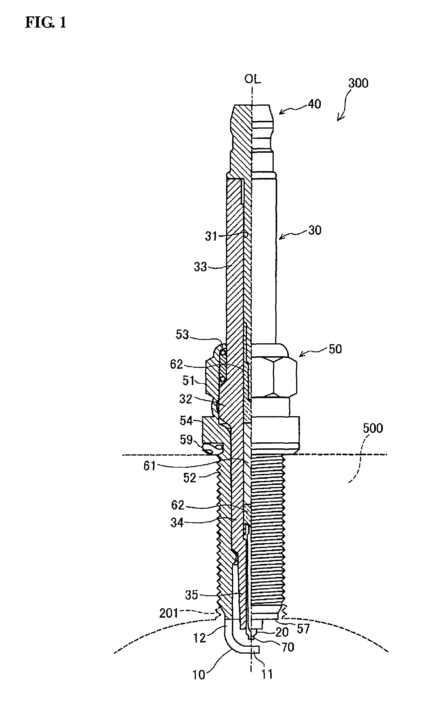
[0035]FIG. 1 is a schematic view showing the overall structure of a spark plug 300 according to one exemplary embodiment of the present invention. The right and left sides of FIG. 1 with respect to a center axis OL of the spark plug 300 show a side view and a section view of the spark plug 300, respectively. It is herein noted that, in the following explanation, the terms “front” and “rear” respectively refer to the side of location of the after-mentioned ground electrode 10 (i.e. the bottom side of FIG. 1) and the side of location of the after-mentioned metal terminal 40 (i.e. the top side of FIG. 1) with respect to the direction of the axis OL.

[0036]The spark plug 300 includes a ceramic insulator 30, a center electrode 20, a metal shell 50, a ground electrode 10 and a metal terminal 40. The center electrode 20 is held in the ceramic insulator 30. The ceramic insulator 30 is held in the metal shell 50. The ground electrode 10 is joined to a ...


PUM


Abstract

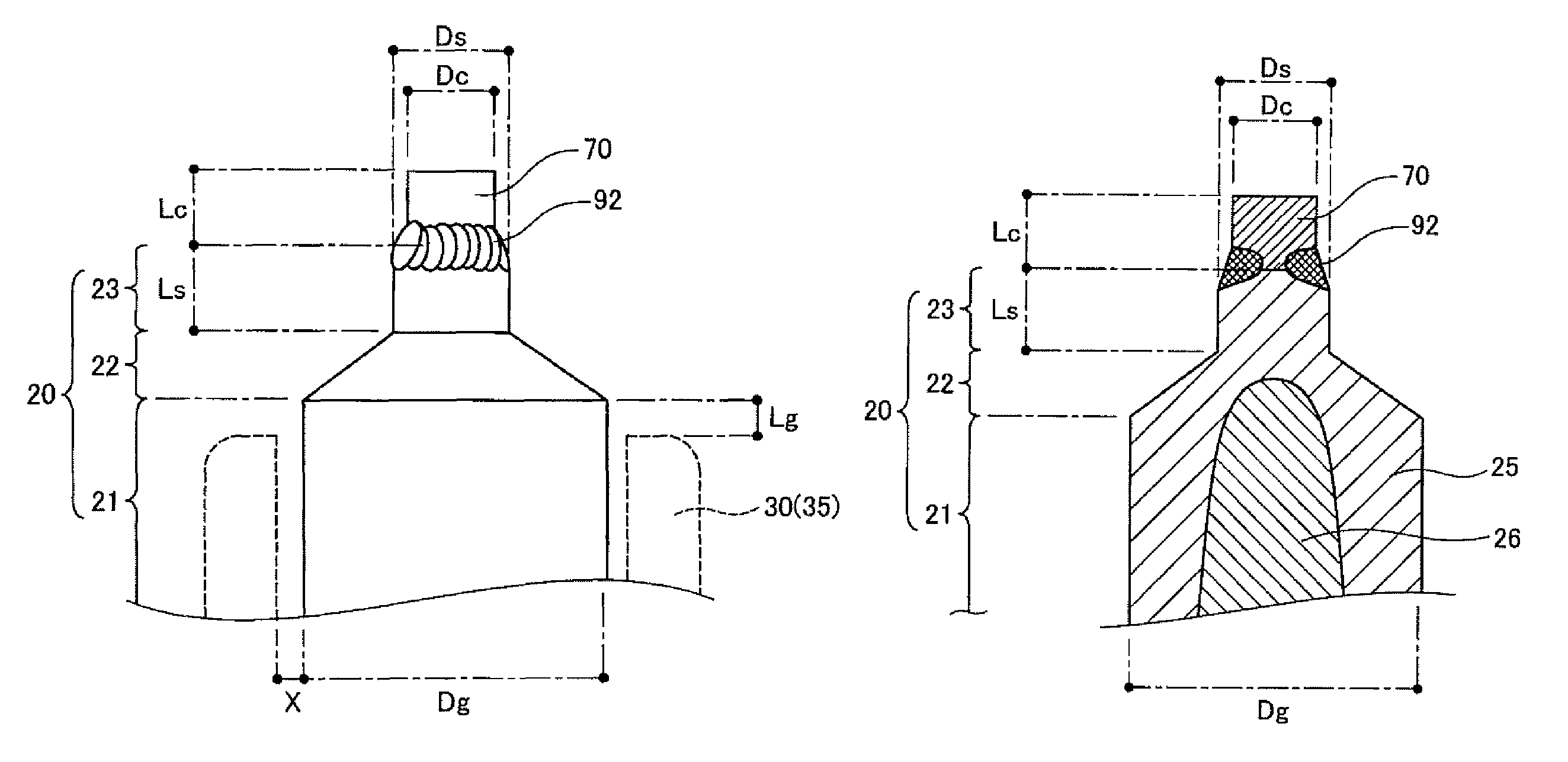
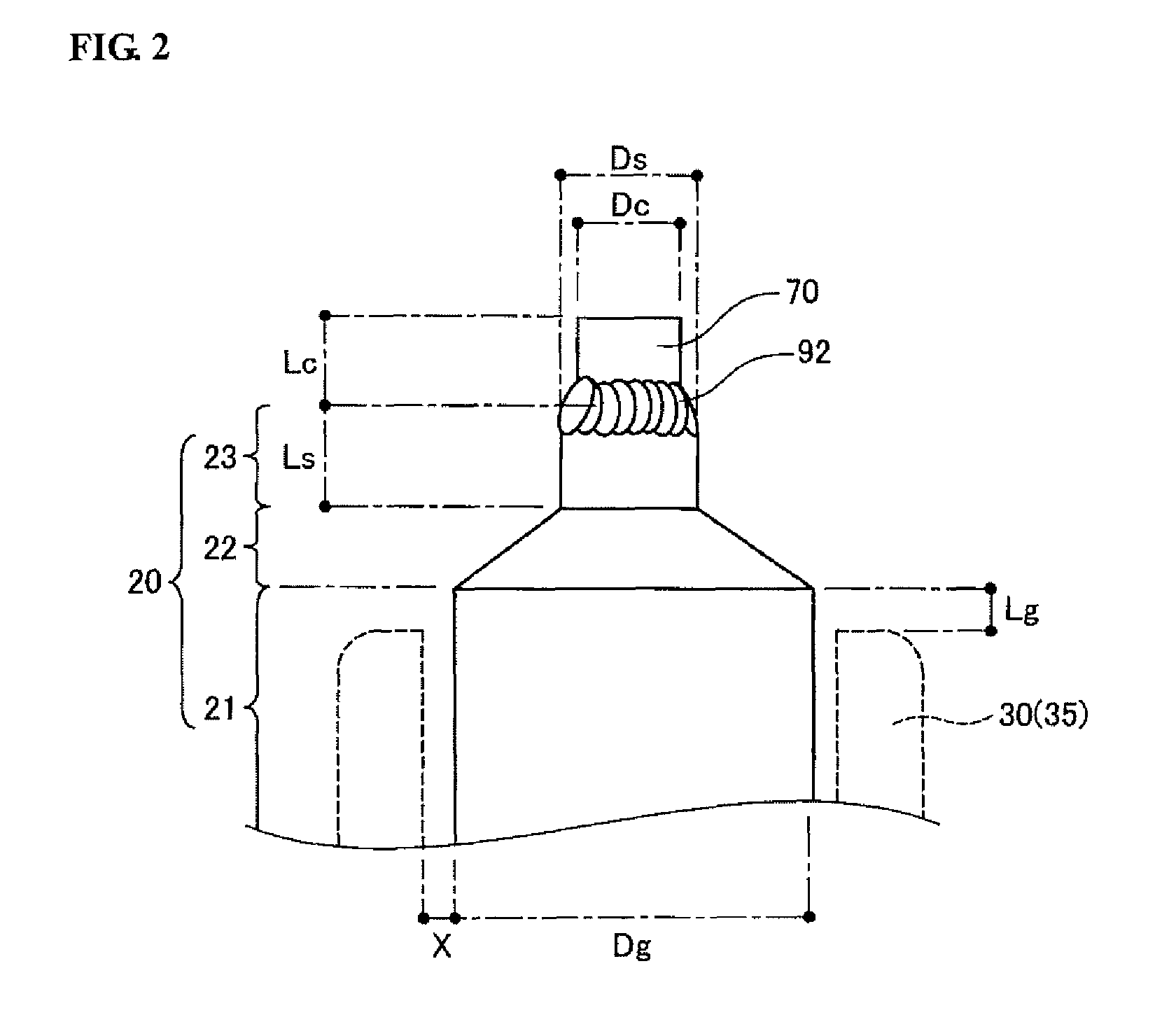
A spark plug with a center electrode, the center electrode having a small-diameter portion with a noble metal tip joined by laser welding to a front end of the small-diameter portion, a large-diameter portion made larger in diameter than the small-diameter portion and a connection portion connecting the small-diameter portion and the large-diameter portion to each other. In this spark plug, the following conditions (1), (2) and (3) are satisfied:Dg≦2.6  (1)1.15≦Lc+Ls≦3.0  (2)0.48≦Ls / (Lc+Ls)≦0.75  (3)where Dg (mm) is a diameter of the large-diameter portion; Lc (mm) is a length of the noble metal tip in an axis direction of the spark plug; and Ls (mm) is a length of the small-diameter portion in the axis direction of the spark plug.

Description

RELATED APPLICATIONS[0001]The present invention claims priority to Japanese Patent Application No. 2013-86562 filed on Apr. 17, 2013, hereby incorporated by reference in its entirety.FIELD OF THE INVENTION[0002]The present invention relates to a spark plug.BACKGROUND OF THE INVENTION[0003]A spark plug is used for ignition in an internal combustion engine such as gasoline engine. In general, the spark plug has a center electrode and a ground electrode with a gap for spark discharge (called “discharge gap”) defined therebetween. In order to ensure good ignition performance, the center electrode usually includes a small-diameter portion located on a front end side (discharge gap side) thereof, a large-diameter portion located in rear of the small-diameter portion and made larger in diameter than the small-diameter portion and a connection portion connecting the small-diameter portion and the large-diameter portion to each other.[0004]It has been proposed to provide the spark plug by la...

Claims


Application Information

Patent Timeline
Patent Type & Authority Patents(United States)
IPC IPC(8): H01T13/20H01T13/39H01T21/02
CPCH01T13/39H01T13/20H01T21/02
Inventor KATAOKA, YOSHIKAZU
Owner NGK SPARK PLUG CO LTD
Learn More