Propellers for aircraft

a propeller and aircraft technology, applied in the direction of propellers, aircraft components, transportation and packaging, etc., can solve the problems of reducing the aerodynamic profile of the propeller, changing direction, and requiring a relatively large spinner size, so as to reduce the drag profile, improve the aerodynamic profile, and reduce the diameter

Active Publication Date: 2016-12-27
GE AVIATION SYST LTD
View PDF67 Cites 5 Cited by
  • Summary
  • Abstract
  • Description
  • Claims
  • Application Information

AI Technical Summary

Benefits of technology

[0010]By providing such a plurality of composite propeller blades mounted in at least two parallel planes, various aspects and embodiments of the present invention can be provided having a reduced diameter spinner with an improved aerodynamic profile that can be matched to an engine nacelle and having a reduced drag profile for both variable and non-variable pitch propellers.

Problems solved by technology

However, whilst composite propeller blades have numerous advantages, the materials used to form them have to be shaped so as to provide generally smooth and gradual transitions in shape from an aerofoil section to a supporting blade root because the fibres that are used cannot be made to change direction abruptly without losing a substantial amount of their mechanical strength.
This results in the composite version of the propeller needing a relatively larger spinner size with an attendant increase in drag, as well as giving rise to design difficulties in matching the spinner to the nacelle of the aircraft when trying to optimise overall aircraft aerodynamic performance.

Method used


Image

  • Propellers for aircraft
  • Propellers for aircraft
  • Propellers for aircraft

Examples


Embodiment Construction

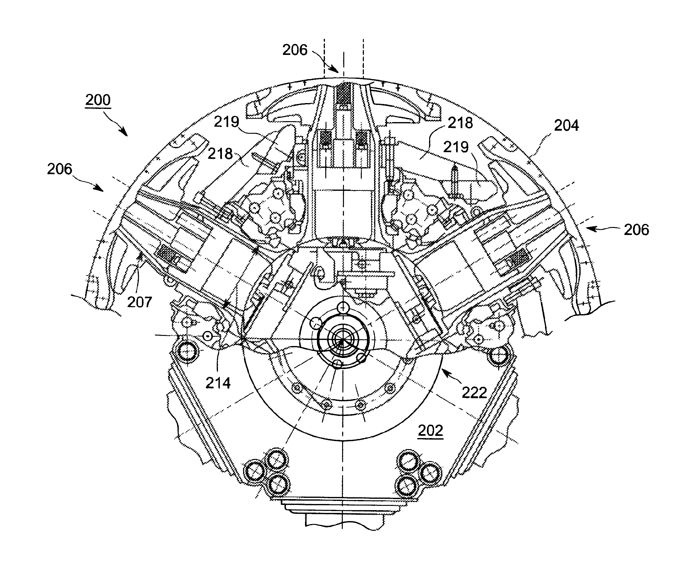
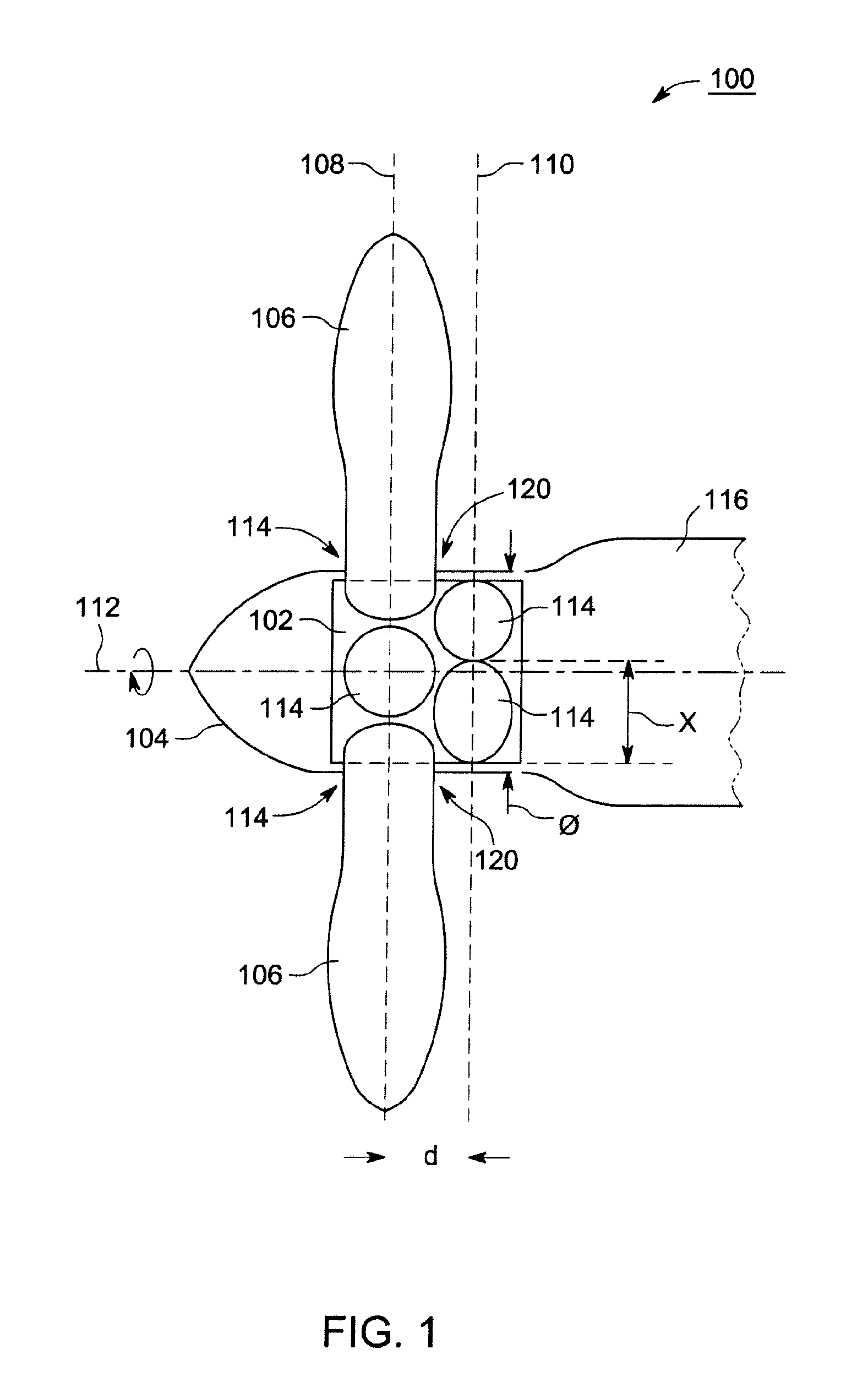
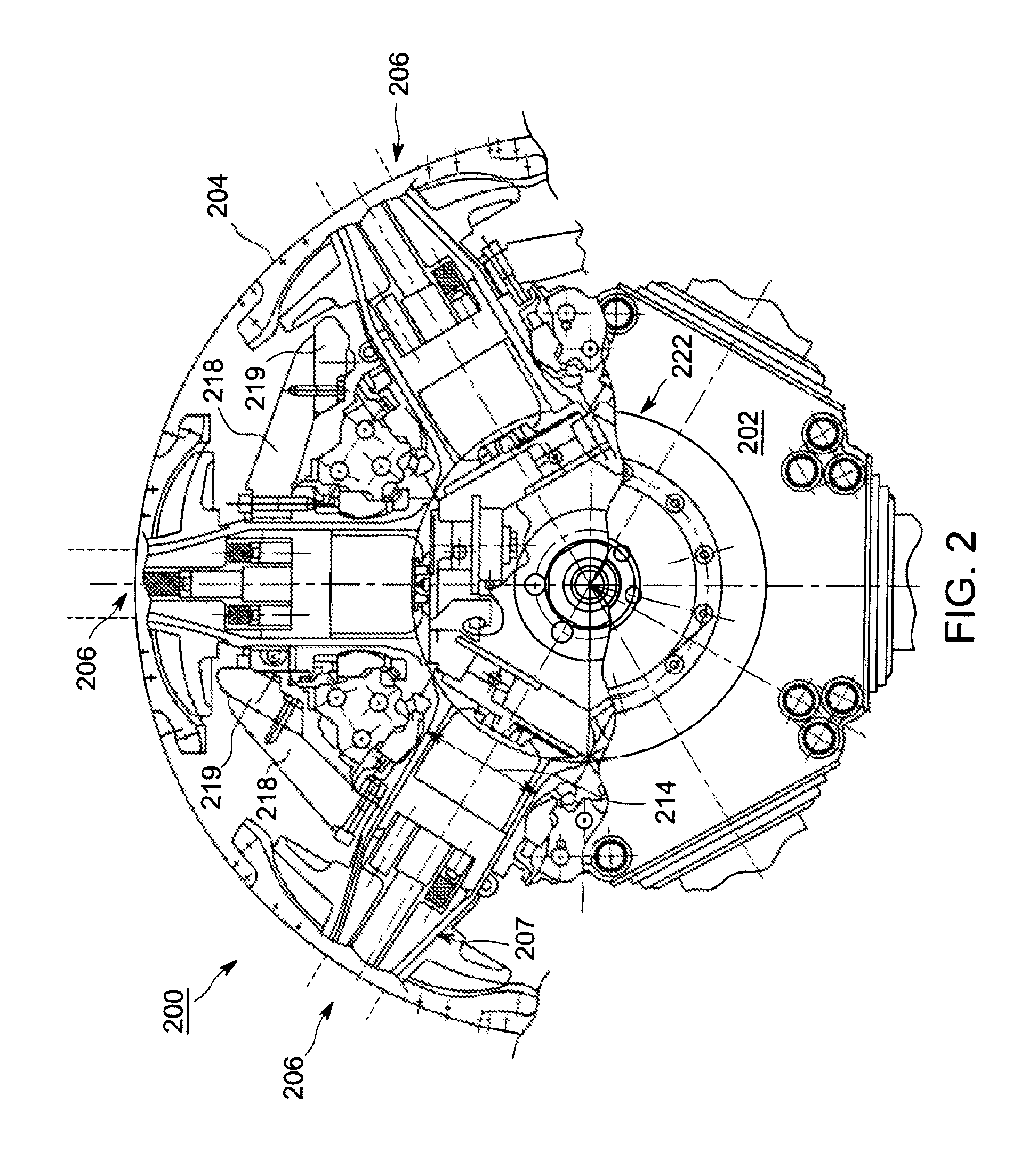
[0016]FIG. 1 shows a schematic diagram illustrating a propeller 100 for an aircraft in accordance with an embodiment of the present invention. The propeller 100 comprises a propeller hub 102 that is rotatably driven by an aircraft engine (not shown) housed in a nacelle 116.

[0017]A spinner 104 is provided encasing the propeller hub 102 for streamlining the propeller 100. In this embodiment, the spinner 104 is fixed to the propeller hub 102 such that they rotate together when the propeller hub 102 is driven by the aircraft engine. The spinner 104, which is generally cone-shaped with a largest diameter denoted by φ, provides a streamlined interface between the rotatable propeller 100 and the fixed position nacelle 116.

[0018]A plurality of composite propeller blades 106 are mounted to the propeller hub 102, and project through the spinner 104, such that the spinner 104 provides streamlining for air flowing near to roots 120 of the blades 106. For example, the blades 106 may comprise wov...


PUM


Abstract

One aspect of the present invention provides a propeller for an aircraft. The propeller comprises a propeller hub, a spinner for streamlining the propeller and a plurality of composite propeller blades mounted to the propeller hub. The propeller blades are arranged to rotate together in the same rotational direction in at least two parallel planes substantially perpendicular to an axis of rotation of the propeller. The propeller has a reduced sized spinner with an improved aerodynamic profile that can be better matched to an engine nacelle and also has reduced drag.

Description

BACKGROUND OF THE INVENTION[0001]Field of the Invention[0002]The field of the present invention relates generally to propellers for aircraft. More particularly, the field of the present invention relates to a propeller having a plurality of composite propeller blades.[0003]Description of Related Art[0004]In aviation it is known to use propellers having one or more propeller blades to generate an airflow to which an airframe can react, for example, so as to generate a forward thrust to propel an aircraft. It is also known that such propellers may be of variable pitch such that the angle of attack of the propeller blades relative to an airflow can be adjusted in order to optimise propeller performance when operating at any particular speed.[0005]Recently, improvements in propeller blade design have led to the increased use of composite materials to form the blades. The composite materials have weight advantages when compared to conventional metallic propeller blades.[0006]However, whi...

Claims


Application Information

Patent Timeline
Patent Type & Authority Patents(United States)
IPC IPC(8): B64C11/06B64C11/48
CPCB64C11/06B64C11/48
Inventor TOWKAN, MICHAEL FEDOR
Owner GE AVIATION SYST LTD
Why Eureka
Try Eureka