
Optical fiber manufacturing method and optical fiber

a technology of optical fiber and manufacturing method, which is applied in the direction of manufacturing tools, glass optical fibre, cladded optical fibre, etc., can solve the problems of affecting the production efficiency of optical fiber, and the difficulty of realizing such optical fiber production facilities, and achieve excellent hydrogen resistance

Active Publication Date: 2016-12-27
SUMITOMO ELECTRIC IND LTD
View PDF62 Cites 2 Cited by
  • Summary
  • Abstract
  • Description
  • Claims
  • Application Information

AI Technical Summary

Benefits of technology

The present invention is about creating a special type of optical fiber that has low-loss and is resistant to hydrogen. This fiber has a pure silica core and is doped with alkali metals. This patent is important because it describes how to create a better optical fiber for use in various applications.

Problems solved by technology

However, in the former, it is difficult to realize such optical fiber production facilities.
In the latter, the productivity considerably degrades.

Method used


Image

  • Optical fiber manufacturing method and optical fiber
  • Optical fiber manufacturing method and optical fiber
  • Optical fiber manufacturing method and optical fiber

Examples


Embodiment Construction

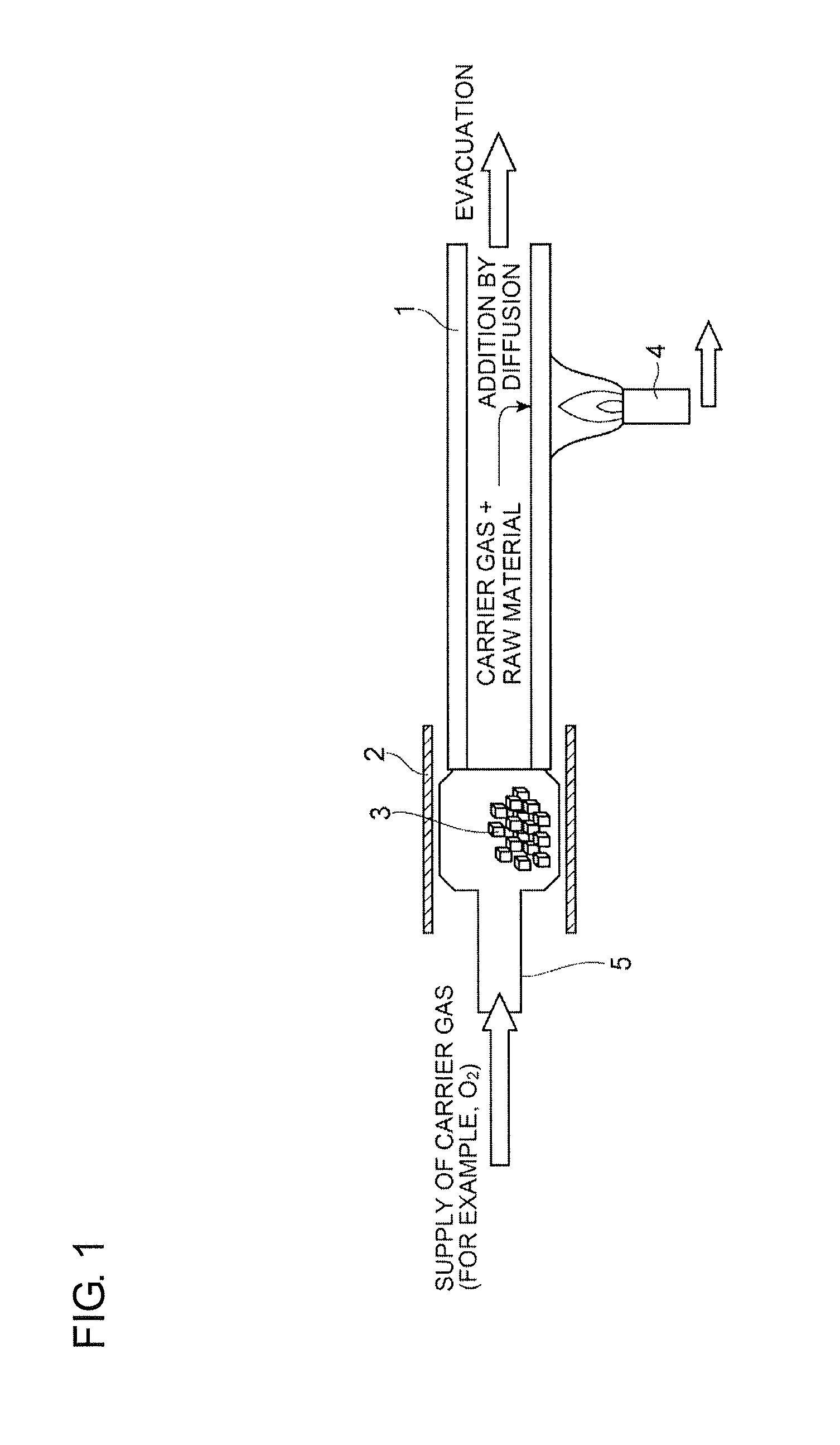
[0025]Hereafter, embodiments of the present invention will be described with reference to the attached drawings. The drawings are used to describe the invention and do not limit the scope of the invention. The dimensional ratios in the drawings are not necessarily exact.

[0026]Alkali metals have relatively high mobility in a silica glass network. Therefore, the silica glass network containing an alkali metal is easily broken and defect centers such as a non-bridging oxygen hole center are easily caused. Thus, according to the findings of the present inventors, the alkali metal-doped silica core optical fiber may have poor hydrogen resistance compared with the pure silica core optical fiber.

[0027]The hydrogen resistance indicates the stability of the transmission loss of optical fibers against hydrogen atoms and is one of the items concerning long-term reliability of optical fibers. Hydrogen gas generated from, for example, a coating material around a glass portion and a metal in an o...


PUM

PropertyMeasurementUnit
partial pressureaaaaaaaaaa
temperatureaaaaaaaaaa

Abstract

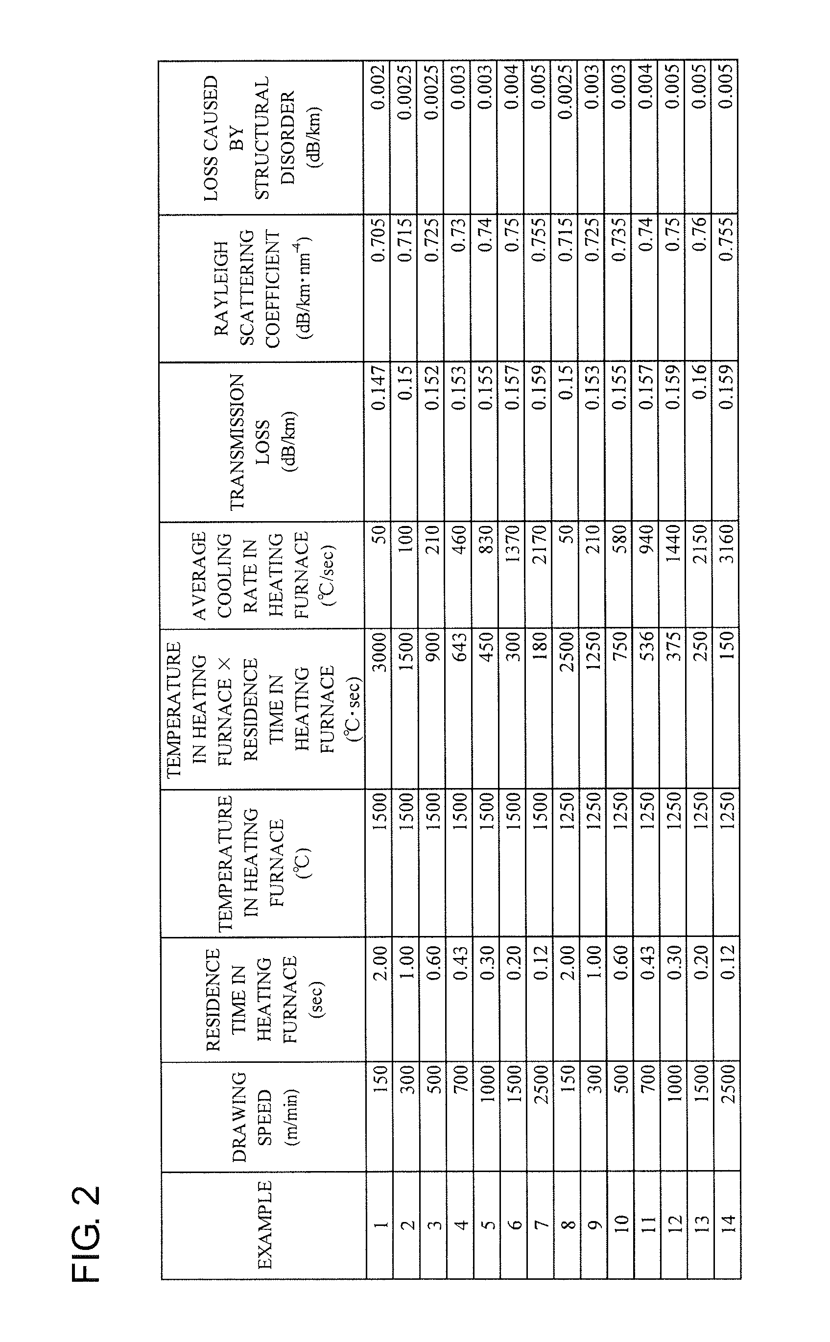
There is provided a method for producing a low-loss alkali metal-doped silica core optical fiber having excellent hydrogen resistance. The method for producing the optical fiber according to the present invention includes a drawing step of drawing an optical fiber preform in a drawing furnace to produce a silica glass-based optical fiber including a core region containing an alkali metal with an average concentration of 0.5 atomic ppm or more and a cladding region that surrounds the core region and a heating step of heating the optical fiber in a heating furnace through which the optical fiber drawn from the drawing furnace passes.

Description

TECHNICAL FIELD[0001]The present invention relates to a method for producing an optical fiber and an optical fiber.BACKGROUND ART[0002]An optical fiber (e.g., optical fiber conforming to ITU-T G.652 standard) including a core made of silica glass containing GeO2, which is a dopant for increasing the refractive index, is referred to as a “GeO2-doped silica core optical fiber” in this Description. An optical fiber including a core made of substantially pure silica glass without containing a dopant for increasing the refractive index (e.g., GeO2 and Al2O3) is referred to as a “pure silica core optical fiber” in this Description. The pure silica core optical fiber has low transmission loss and good long-term reliability such as hydrogen resistance and radiation resistance compared with the GeO2-doped silica core optical fiber (refer to Y. Chigusa, et al., J. LIGHTW. TECHNOL., VOL. 23, NO. 11, pp. 3541-3550, 2005). The GeO2-doped silica core optical fiber is sometimes exposed to deuteriu...

Claims


Application Information

Patent Timeline
Patent Type & Authority Patents(United States)
IPC IPC(8): C03C3/06G02B6/02C03B37/027C03C13/04
CPCC03C3/06C03B37/02727C03C13/045G02B6/02395Y02P40/57C03B2201/50C03B2205/55C03B2205/56C03C2201/21C03C2201/23C03C2201/50C03C2203/54C03C13/046
Inventor HARUNA, TETSUYAHIRANO, MASAAKITAMURA, YOSHIAKINAKANISHI, TETSUYA
Owner SUMITOMO ELECTRIC IND LTD
Learn More