Fuel cell assembly comprising an improved catalytic burner

a fuel cell and burner technology, applied in the direction of fuel cells, mixers, mixing methods, etc., to achieve the effect of reducing pressure losses, optimizing suction by fans, and uniform flow against the cell stack

Inactive Publication Date: 2017-01-10
MTU ONSITE ENERGY
View PDF13 Cites 0 Cited by
  • Summary
  • Abstract
  • Description
  • Claims
  • Application Information

AI Technical Summary

Benefits of technology

[0017]It is proposed according to the one embodiment of the disclosure not to draw off the mixture of fresh air, anode waste gas and cathode exhaust after passing through the catalytic burner directly by the fan, but to collect it initially in a suction tube, which discharges into the fan. Mixing and catalytic burning of the drawn-in gas already occurs before the suction tube so that optimal suction by the fan is guaranteed. Because of flow guiding in a suction tube the fan can be arranged next to the protective housing and communicate with the internal space of the housing through standardized suction and discharge connectors. Since the protective housing and the flanged-on fan form two separate assemblies, both assemblies can be designed and optimized independently of each other. An optimized distributor for longitudinal distribution of the gas mixture coming from the fan can be arranged in the space gained above the cell stack so that the suction and outflow properties of the fan itself are not critical. Uniform flow against the cell stack is guaranteed without demanding rectifiers and internals by means of a flow distributor that tapers wedge-like in the longitudinal direction of the fuel cell stack so that pressure losses can be significantly reduced relative to the previous design. The power requirements on the fan are also reduced accordingly. It was surprisingly found that cell stacks with up to 600 individual units can be supplied with a single fan with the arrangement proposed according to the disclosure.
[0018]It is also proposed according to the disclosure to arrange the catalytic burner on the cathode output side between the fuel cell stack and the wall of the protective housing. Because of this arrangement the catalyst is more readily accessible so that maintenance for cleaning purposes is simplified. For example, cleaning / filling openings can be provided in the wall of the protective housing so that disassembly of the cell stack is no longer required. Cleaning of the catalyst can therefore be carried out by the user. In contrast to the previously used fuel cell arrangement the catalytic burner is traversed from the top down so that the use of pelletized catalysts is now also made possible. In the prior art pelletized catalysts could not be used, since suspension of the catalyst particles in the air stream occurs during flow from the bottom up, which entails strong mechanical wear on the catalyst elements. However, the previously preferably used honeycomb catalysts can likewise also be used in the present disclosure.
[0019]A simple gas mixer with lower pressure losses is also furnished according to the disclosure. The gas mixer has a first mixing zone in which cathode exhaust is mixed with fresh air, as well as a second mixing zone in which anode waste gas is introduced to the mixture of cathode exhaust and fresh air. The mixer is preferably arranged on the cathode output side between the cell stack and the wall of the protective housing above the catalytic burner also provided there. Long mixing zones can therefore be implemented so that fewer internals and mixing elements are required in order to guarantee homogeneous mixing of the cathode and anode waste gas streams and the fresh air. The pressure loss in the mixture relative to the known mixers arranged on the fuel cell stack is therefore significantly reduced. In addition, the mixer according to the disclosure can be made light and can be easily and cost effectively manufactured because of the simple sheet metal parts, which reduces the overall cost of the fuel cell arrangement.

Problems solved by technology

The underlying technical problem of the present disclosure is therefore to further improve the described design principle of a fuel cell stack integrated in a protective housing with cathode gas stream circulating in the protective housing.

Method used


Image

  • Fuel cell assembly comprising an improved catalytic burner
  • Fuel cell assembly comprising an improved catalytic burner
  • Fuel cell assembly comprising an improved catalytic burner

Examples


Embodiment Construction

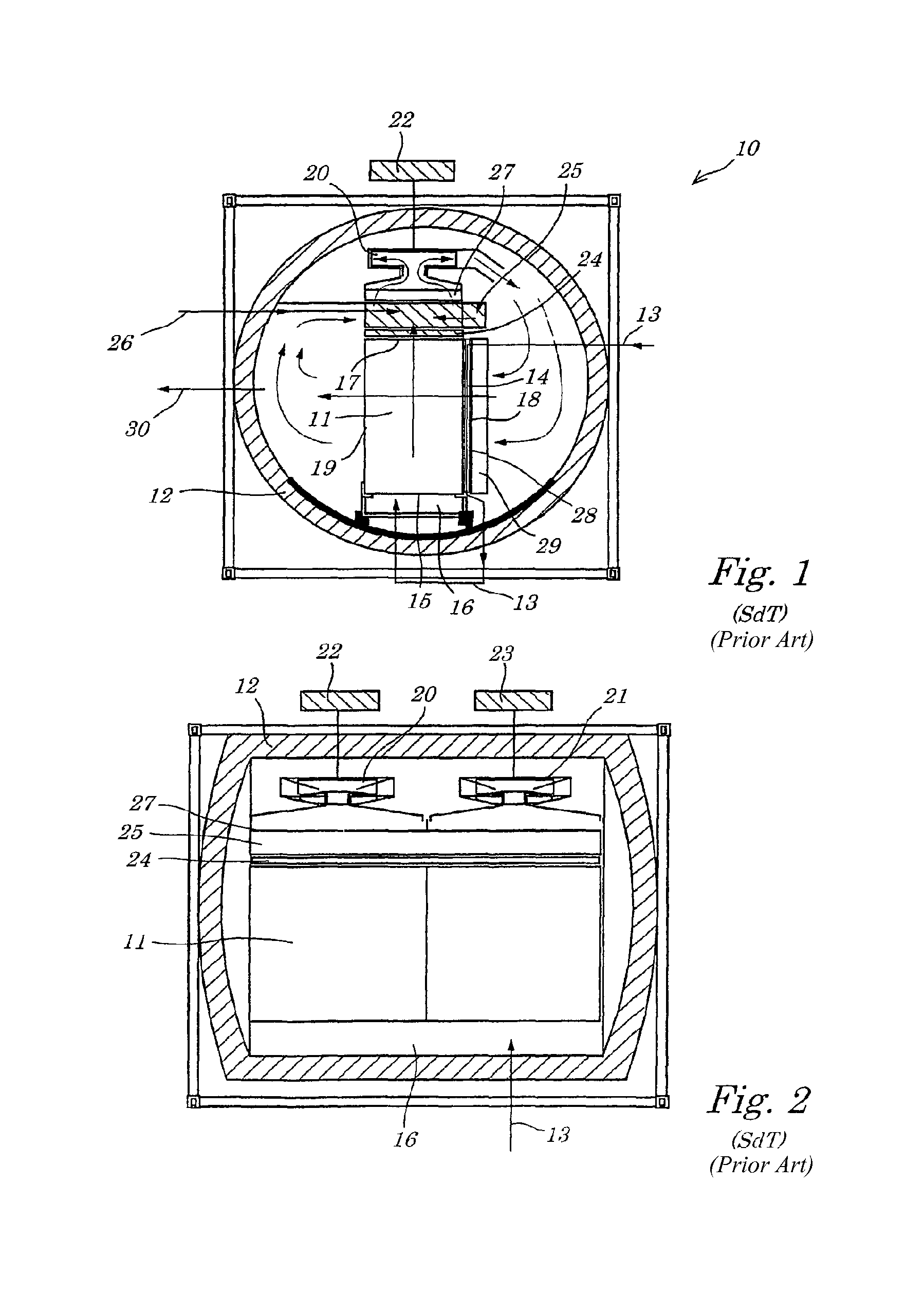
[0035]The fuel cell according to the prior art was already described above in conjunction with FIGS. 1 and 2.

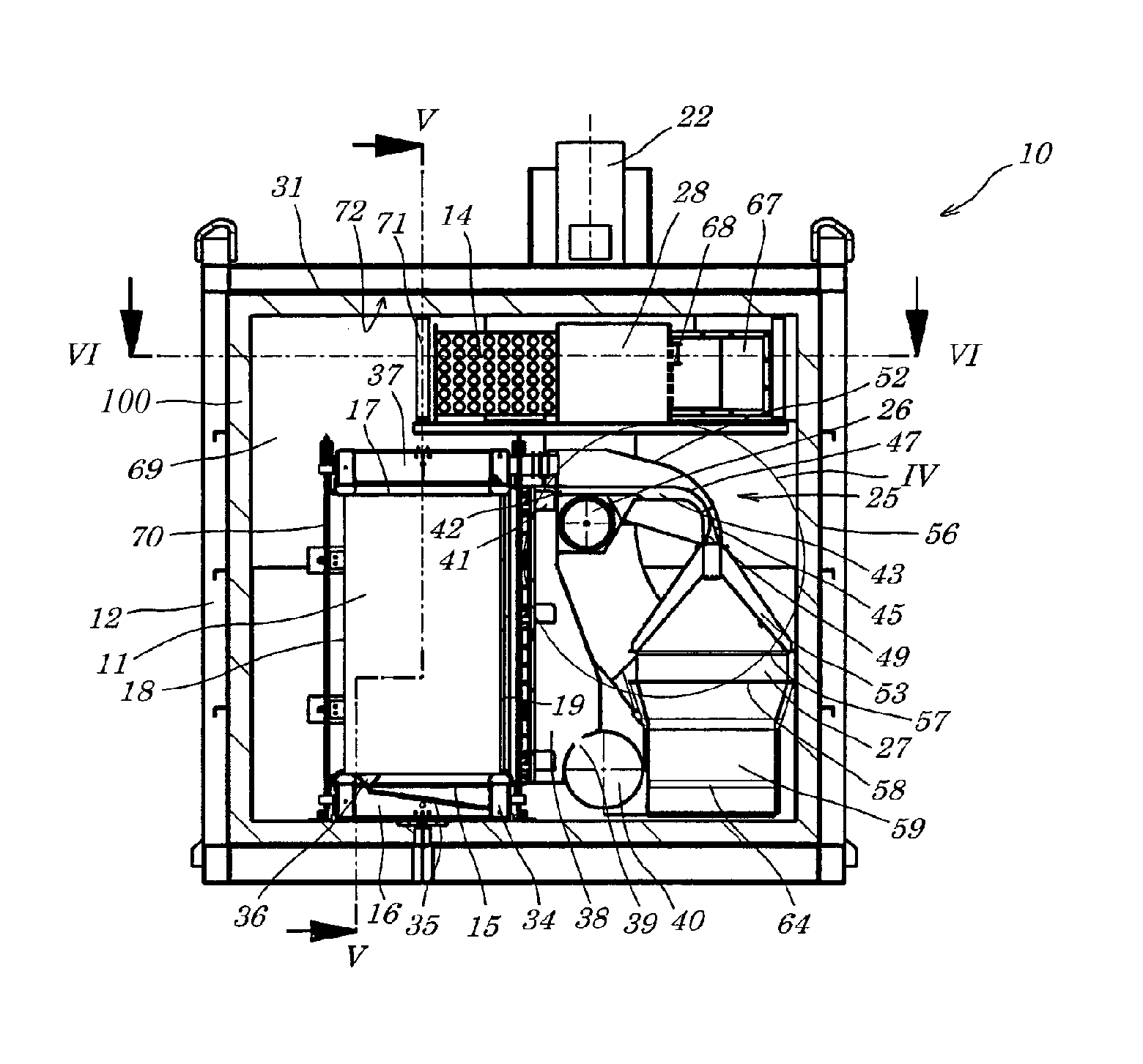
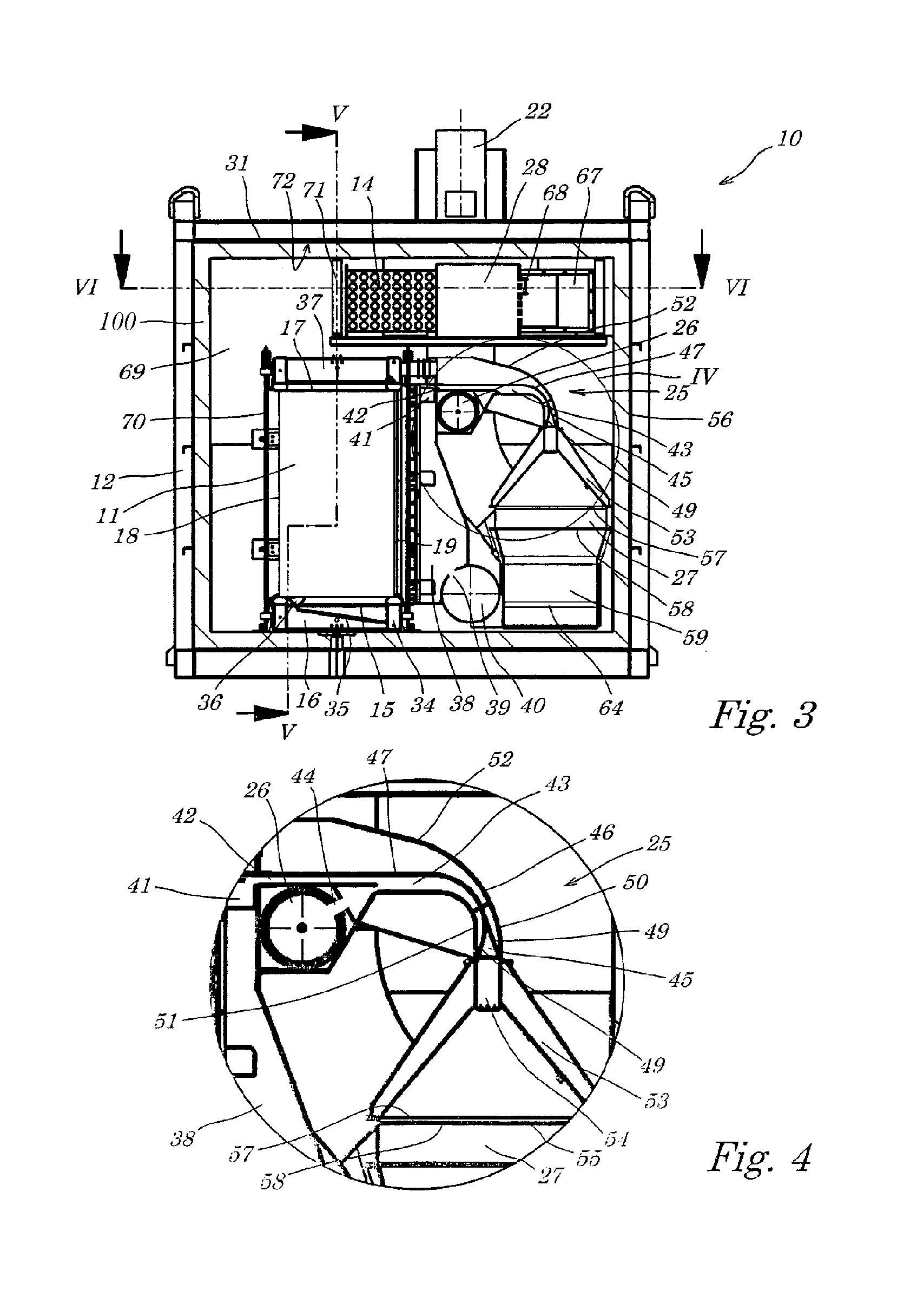
[0036]With reference to FIGS. 3 to 7 two preferred variants of the fuel cell arrangement according to the disclosure are described below. Components that are identical to components of the fuel cell arrangement of the prior art or have the same or similar function are then referred to with the same reference numbers.

[0037]The fuel cell arrangement designed overall with reference number 10, like the fuel cell arrangement of the prior art, has a horizontally lying fuel cell stack 11 consisting of vertically arranged plate-like elements, which is arranged in a heat-insulated, gas-tight protective housing 12. In contrast to the protective housing of the fuel cell arrangement of the prior art, the protective housing of the fuel arrangement 10 according to the disclosure is designed essentially rectangular. The gas-tight protective housing 12 consists of individual metal plates 31 ...


PUM

PropertyMeasurementUnit
temperaturesaaaaaaaaaa
operating temperatureaaaaaaaaaa
electrical poweraaaaaaaaaa

Abstract

There is disclosed a fuel cell assembly comprising at least one horizontally arranged fuel cell stack that has numerous fuel cells, each comprising an anode, a cathode and an electrolyte situated between the anode and the cathode; combustible gas supply means for supplying combustible gas to the anodes of the fuel cells; anode gas withdrawal means for withdrawing the anode exhaust gas from the anodes; cathode gas supply means for supplying cathode gas to the cathodes of the fuel cells; cathode gas withdrawal means for withdrawing the cathode exhaust gas from the fuel cells; and recirculation means for recirculating at least one part of the anode exhaust gas and/or the cathode exhaust gas to cathodes of the fuel cells. The fuel cell assembly according to the invention is characterized in that the recirculation means comprise at least one catalytic burner with catalyst material for burning the remaining combustible gas contained in the anode exhaust gas, said burner being situated at the side of the fuel cell stack.

Description

CROSS-REFERENCE TO RELATED APPLICATIONS[0001]This application claims priority to German patent applications DE 10 2008 047 920.9 filed on Sep. 19, 2008 and DE 10 2009 013 598.7 filed on Mar. 17, 2009 and PCT application PCT / EP2009 / 006701 filed on Sep. 16, 2009, which are hereby incorporated by reference in their entireties.BACKGROUND[0002]To generate electrical power by means of fuel cells a larger number of fuel cells are ordinarily arranged in the form of a stack, each fuel cell having an anode, a cathode and an electrolyte arranged in between. The individual fuel cells are each separated by bipolar plates and electrically contacted. Current collectors are provided on the anodes and cathodes, which serve for electrical contact of the anodes and cathodes, on the one hand, and to supply reaction gases to them, on the other. Sealing elements are provided in the edge area of the anode, cathode and electrolyte matrix, which form lateral sealing of the fuel cells and therefore the fuel ...

Claims


Application Information

Patent Timeline
Patent Type & Authority Patents(United States)
IPC IPC(8): H01M8/06B01F5/06B01F3/02H01M8/04B01F15/02H01M8/24H01M8/14B01F23/10
CPCH01M8/04097B01F3/02B01F5/0646H01M8/0662H01M8/2485H01M8/2475H01M2008/147H01M2300/0051Y02E60/50Y02E60/526B01F2015/0221H01M8/04014H01M8/04022H01M8/247H01M8/249H01M8/2484B01F23/10B01F25/433B01F35/715H01M8/04H01M8/06H01M8/24H01M8/14H01M8/244
Inventor BURMEISTER, UWEHUBER, JOHANNOTTMANN, NORBERTPETERHANS, STEFAN-IBRAHIMWAGNER, WOLFGANGWEISER, CHRISTOPH
Owner MTU ONSITE ENERGY
Why Eureka
Try Eureka