
Hybrid vehicle mode-switching control device

a control device and hybrid technology, applied in the direction of engine-driven generators, propulsion parts, transportation and packaging, etc., can solve the problems of driver discomfort, surplus or deficit of vehicle wheel drive power, and state of disabled shift control, so as to reduce the reduce any surplus or deficit of drive power, and reduce the effect of discomfor

Active Publication Date: 2017-01-17
NISSAN MOTOR CO LTD
View PDF6 Cites 4 Cited by
  • Summary
  • Abstract
  • Description
  • Claims
  • Application Information

AI Technical Summary

Benefits of technology

[0014]An object of the present invention is to provide an improved mode-switching control device for a hybrid vehicle, with which drive power surpluses or deficits caused by the aforementioned transmission gear ratio deviation during EV→HEV mode switching can be reduced, and the aforedescribed problems avoided.
[0017]The mode-switching control device of the present invention is characterized by the feature that, when the mode is switched from the electric operation mode to the hybrid operation mode, the output of the electric motor and / or the engine is controlled to a value dependent on the vehicle running state, and in the event that the actual transmission gear ratio of the transmission differs from a target transmission gear ratio corresponding to the vehicle running state, the output of the electric motor and / or the engine is corrected to reduce the surplus or deficit of drive power caused by transmission gear ratio deviation between the actual transmission gear ratio and the target transmission gear ratio.
[0018]In the mode-switching control device for a hybrid vehicle according to the present invention, when mode-switching from the electric operation mode to the hybrid operation mode, the output of the electric motor and / or the engine is controlled to a value dependent on the vehicle running state, and in the event that the actual transmission gear ratio of the transmission differs from a target transmission gear ratio corresponding to the vehicle running state, the output of the electric motor and / or the engine is corrected so as to reduce any drive power surplus or deficit due to transmission gear ratio deviation between the two. Therefore, surplus or deficit of drive power caused by transmission gear ratio deviations during the aforementioned mode-switching is eliminated, a change in drive power level that is commensurate to the driver's control input can be produced, and discomfort associated with generation of a drive power level different from the driver's control input can be eliminated.

Problems solved by technology

However, Patent Document 1 does not mention drive power control at times of EV→HEV mode switching, or shift control of the transmission, giving rise to the following problem.
This, combined with the fact that the transmission is not rotating, leads to a state of disabled shift control.
For these reasons, a significant discrepancy arises between the actual transmission gear ratio at the time that, upon completion of startup when the engine attains complete explosion, a sufficient amount of working oil is discharged from the oil pump and the transmission has become capable of shift control, and a target transmission gear ratio corresponding to the running state, resulting in a surplus or deficit of vehicle wheel drive power with respect to the target transmission gear ratio corresponding to the running state, the surplus or deficit being equivalent to the transmission gear ratio deviation between the actual transmission gear ratio and the target transmission gear ratio.
In conventional hybrid vehicles, of which that disclosed in Japanese Laid-Open Patent Application No. 2000-199442 is representative, no attempt is made to eliminate drive power surpluses or deficits caused by the aforementioned transmission gear ratio deviation during EV→HEV mode switching, which may cause the driver to experience discomfort associated with an inability to obtain a drive power level that is commensurate to the driver's control input.

Method used


Image

  • Hybrid vehicle mode-switching control device
  • Hybrid vehicle mode-switching control device
  • Hybrid vehicle mode-switching control device

Examples


embodiment 1

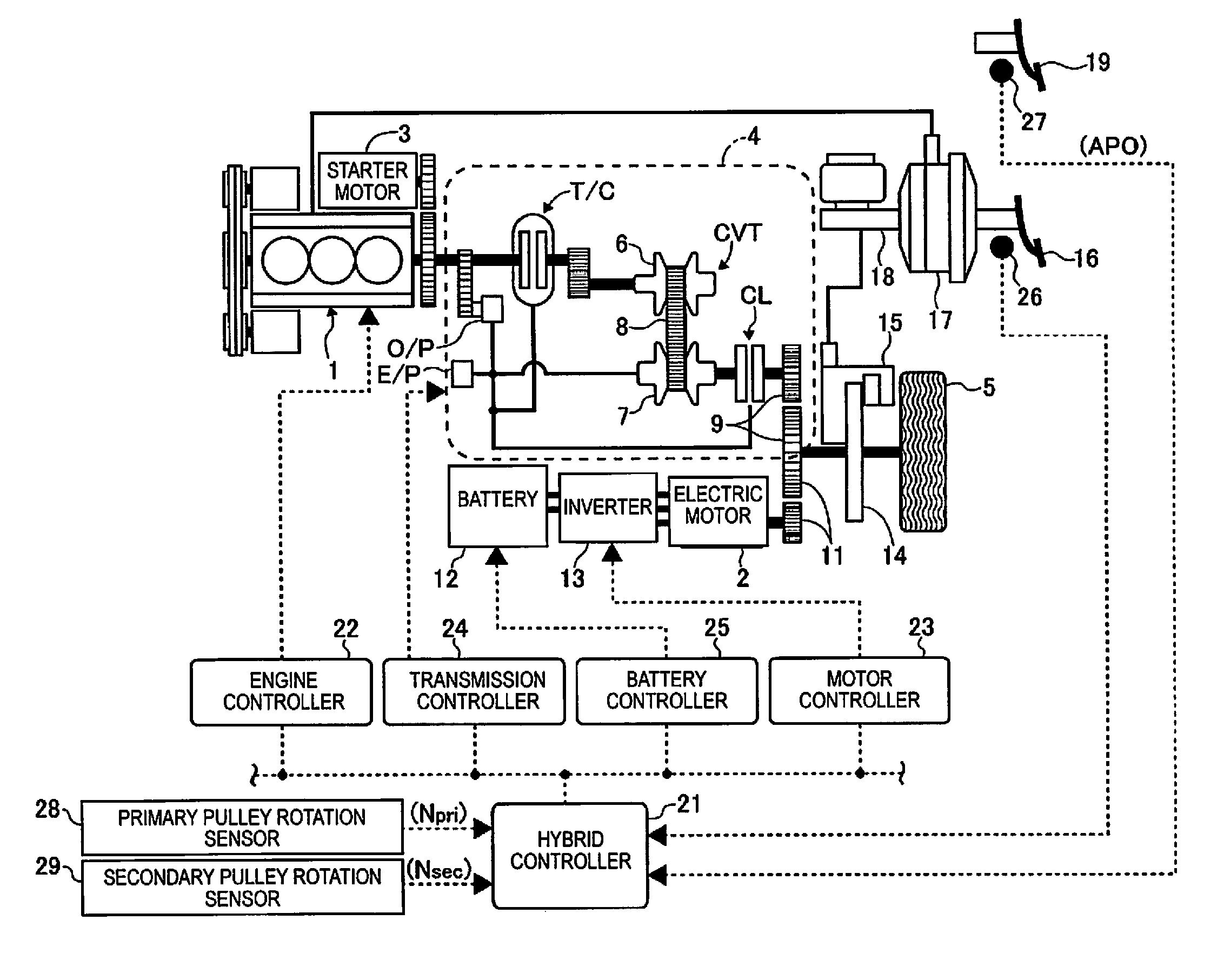
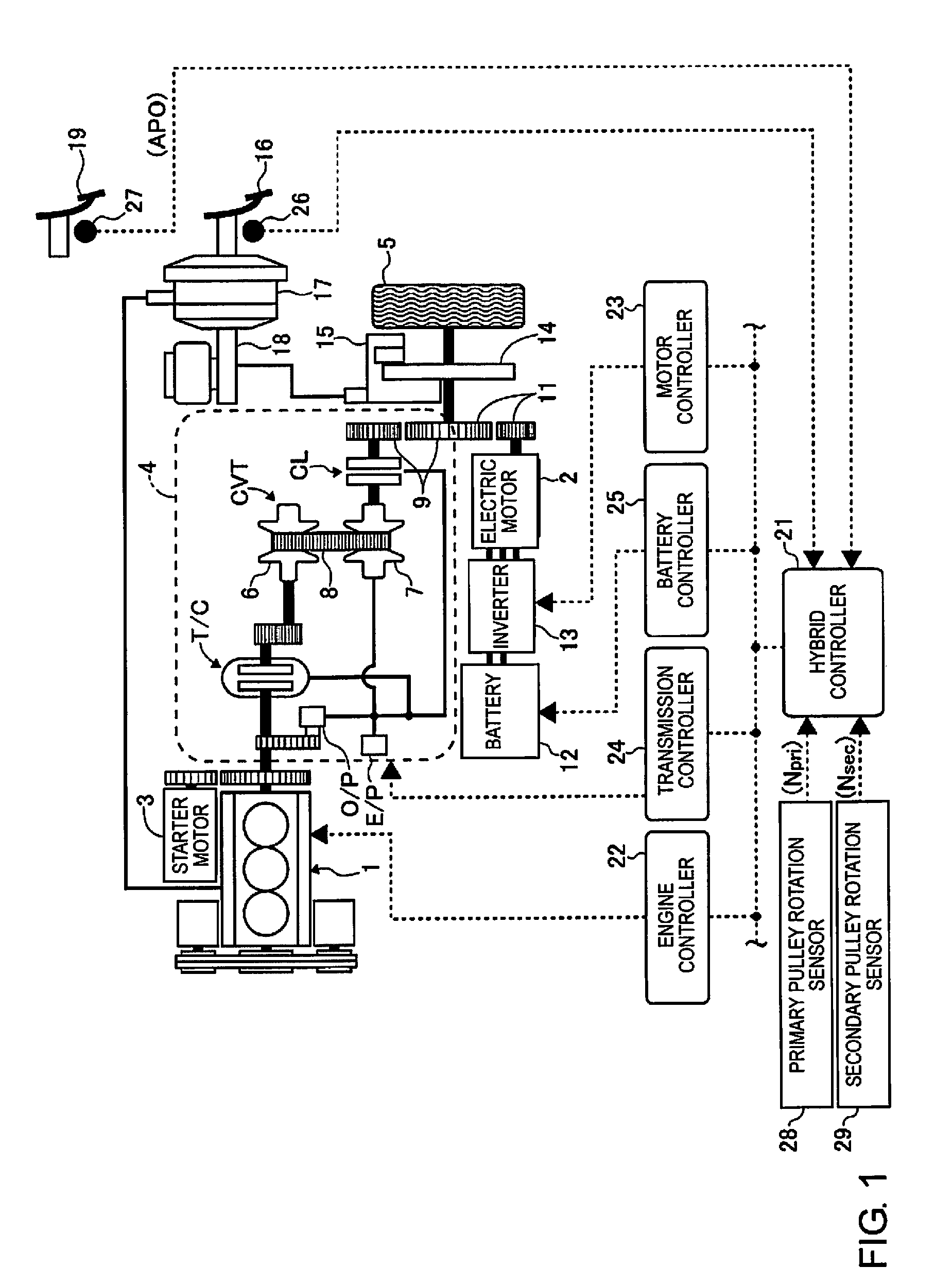
[0026]FIG. 1 is a schematic system diagram showing the drive system of a hybrid vehicle equipped with the mode-switching control device according to an embodiment of the present invention, and the overall control system thereof.

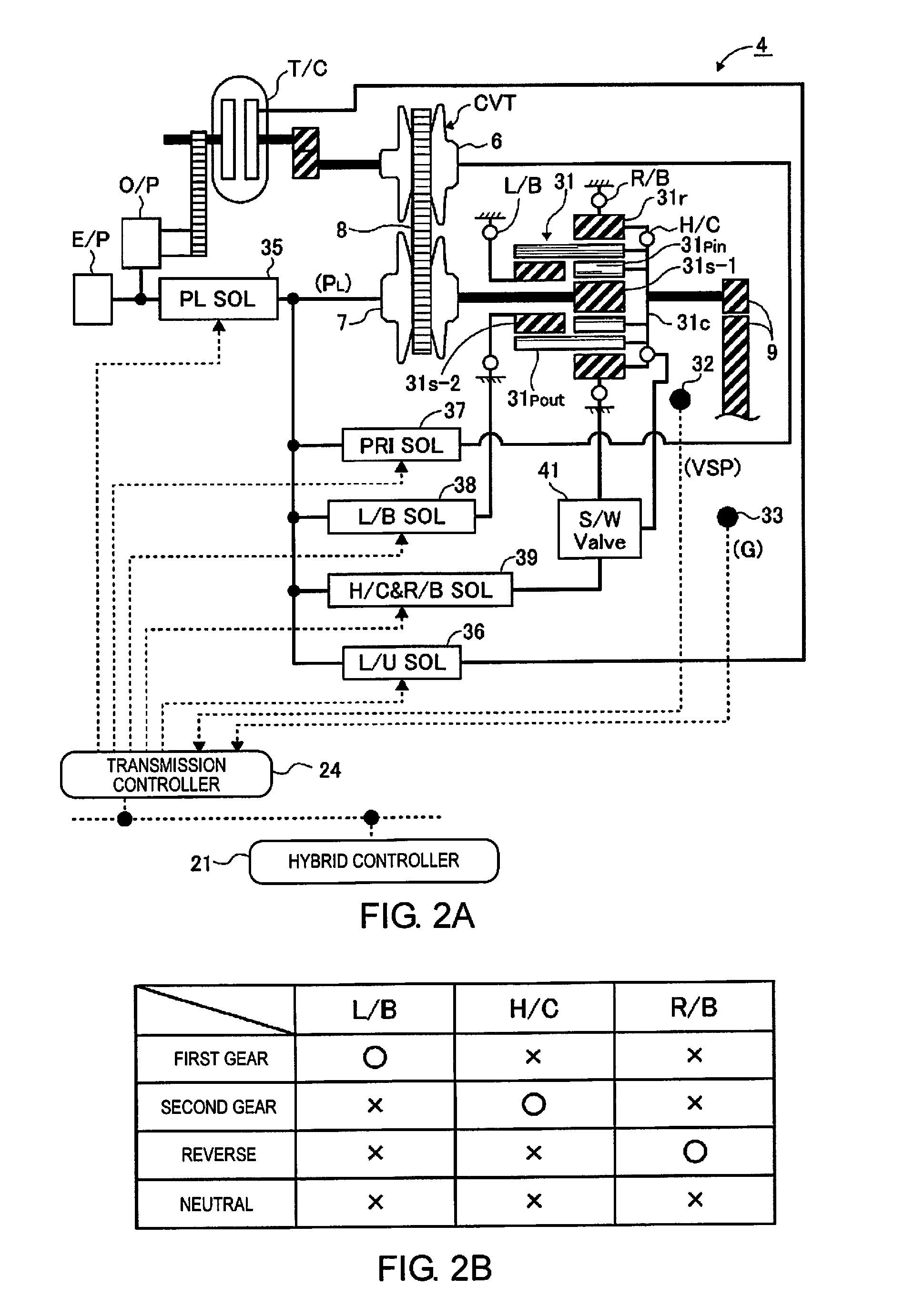
[0027]The hybrid vehicle of FIG. 1 is provided with an engine 1 and an electric motor 2 as on-board power sources, the engine 1 being started by a starter motor 3. The engine 1 is appropriately decouplably drive-coupled to drive wheels 5 via a V-belt continuously variable transmission 4; the scheme of the V-belt continuously variable transmission 4 is as described below.

[0028]The V-belt continuously variable transmission 4 has as the primary constituent element a continuously variable transmission mechanism CVT comprising a primary pulley 6, a secondary pulley 7, and a V-belt 8 suspended between the pulleys 6, 7. The primary pulley 6 is linked to a crankshaft of the engine 1 via a lockup torque converter T / C, and the secondary pulley 7 is linked to the drive ...


PUM


Abstract

A hybrid vehicle mode-switching control device for a hybrid vehicle controls that an output of an engine and / or motor in response to a mode-switch request. In a case of a difference between an actual transmission gear ratio and a target transmission gear ratio, a deficit with respect to the requested drive power occurs that causes discomfort to the driver. The drive power surplus or deficit caused by the transmission gear ratio deviation can eliminated by correcting of the motor torque and / or the engine torque by a correction amount necessary to eliminate the surplus or deficit of drive power. In this way, the lack of drive power due to the transmission ratio deviation and the driver's sense of discomfort can be eliminated.

Description

CROSS-REFERENCE TO RELATED APPLICATIONS[0001]This application is a U.S. National stage application of International Application No. PCT / JP2013 / 079421, filed Oct. 30, 2013, which claims priority to Japanese Patent Application No. 2012-241456 filed in Japan on Nov. 1, 2012.BACKGROUND[0002]Field of the Invention[0003]The present invention relates to a mode-switching control device for a hybrid vehicle, the vehicle having an engine and an electric motor as on-board power sources, and being switchable between an electric operation mode (EV mode) in which the vehicle is operated with the electric motor only, and a hybrid operation mode (HEV mode) in which the vehicle is operated with the electric motor and the engine.[0004]Background Information[0005]Hybrid vehicles of this type known in the prior art include that disclosed, e.g., in Japanese Laid-Open Patent Application No. 2000-199442. This hybrid vehicle has a design in which an engine provided as one of the power sources is decouplabl...

Claims


Application Information

Patent Timeline
Patent Type & Authority Patents(United States)
IPC IPC(8): B60W20/10B60W20/00B60W10/10B60L11/14B60W10/08B60L7/14B60L15/20B60W10/107B60K6/547B60W10/06B60W10/02B60K6/48B60W10/30B60K6/543B60L50/16
CPCB60W20/10B60K6/48B60K6/543B60K6/547B60L7/14B60L11/14B60L15/2009B60W10/02B60W10/06B60W10/08B60W10/10B60W10/107B60W10/30B60W20/00B60W20/19B60W20/30B60W20/40B60K2006/4808B60L2210/40B60L2240/12B60L2240/36B60L2240/421B60L2240/423B60L2240/425B60L2240/441B60L2240/443B60L2240/545B60L2250/26B60W2510/0666B60W2510/085B60W2510/1005B60W2710/0677B60W2710/086B60W2710/1005Y02T10/626Y02T10/6221Y02T10/645Y02T10/70Y02T10/7077Y02T10/7241Y02T10/7275Y10S903/93B60L50/16B60K6/36B60W2710/0666B60W2710/083Y02T10/62Y02T10/64Y02T10/7072Y02T10/72
Inventor TAKANO, AKIRAOSHIO, SHINTAROKODAMA, YOSHIHISAHIRANO, TAKURO
Owner NISSAN MOTOR CO LTD
Learn More