

Method for drying articles
a technology for drying articles and drying sheets, applied in drying, lighting and heating apparatus, furnaces, etc., can solve problems such as microwave frequencies
- Summary
- Abstract
- Description
- Claims
- Application Information
AI Technical Summary
Benefits of technology
Problems solved by technology
Method used
Image

Examples
first embodiment
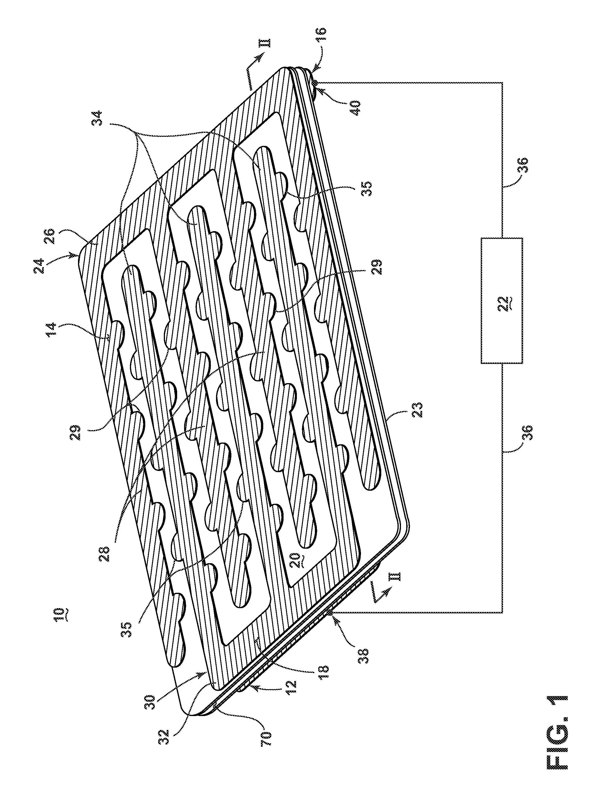
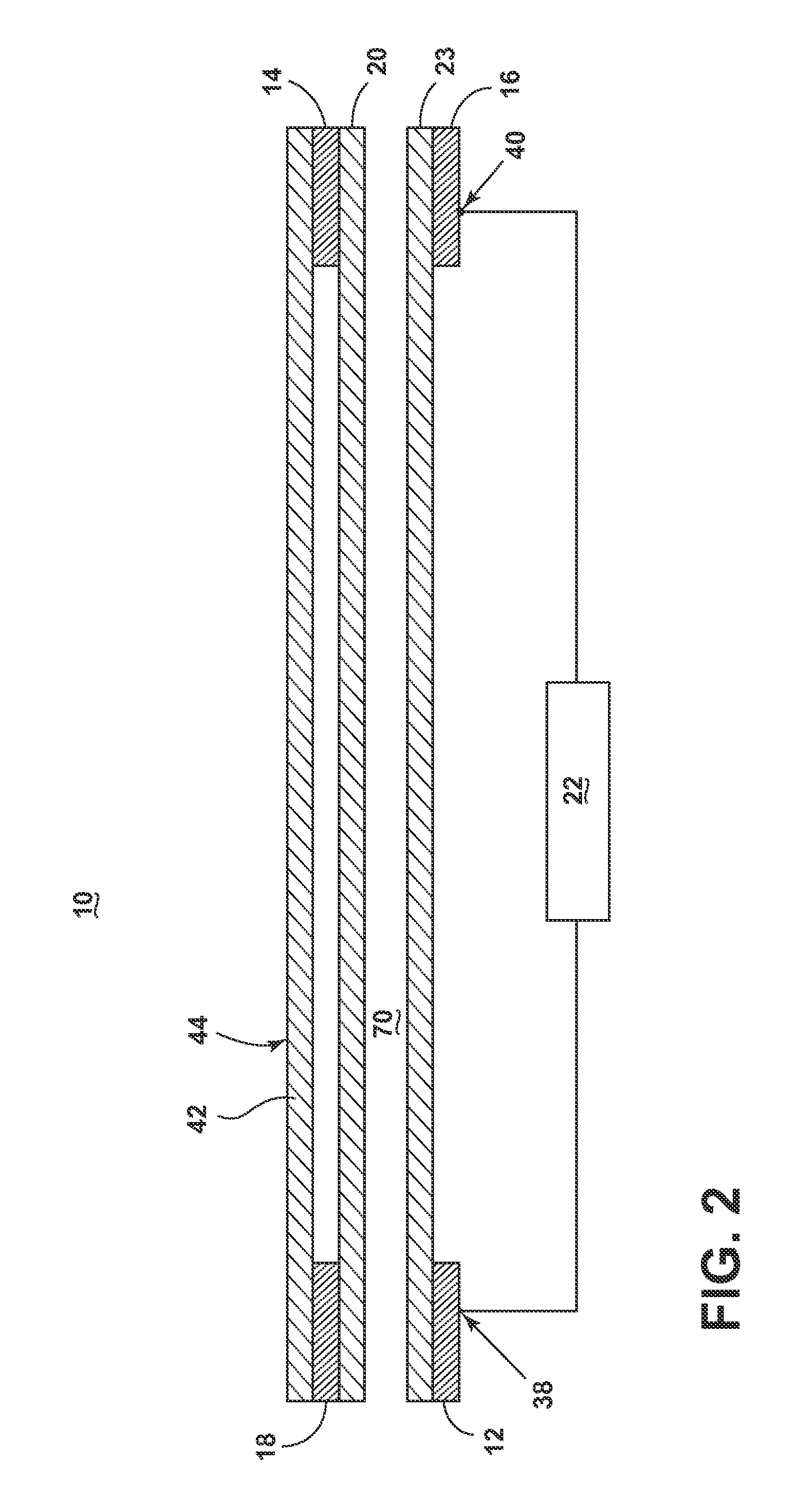
[0017]FIG. 1 is a schematic illustration of a laundry drying applicator 10 according to the invention for dehydrating one or more articles, such as articles of clothing. As illustrated in FIG. 1, the laundry drying applicator 10 has a structure that includes conductive elements, such as a first anode element 12 and a second anode element 18, and an opposing first cathode element 16, a second cathode element 14, in addition to a first non-conductive laundry support element 20, an optional second non-conductive support element 23, and an RF generator 22.
[0018]The second cathode element 14 further includes a first comb element 24 having a first base 26 from which extend a first plurality of teeth 28, and the second anode element 18 includes a second comb element 30 having a second base 32 from which extend a second plurality of teeth 34. The second cathode and second anode elements 14, 18 are fixedly mounted to the first supporting element 20 in such a way as to interdigitally arrange ...
second embodiment
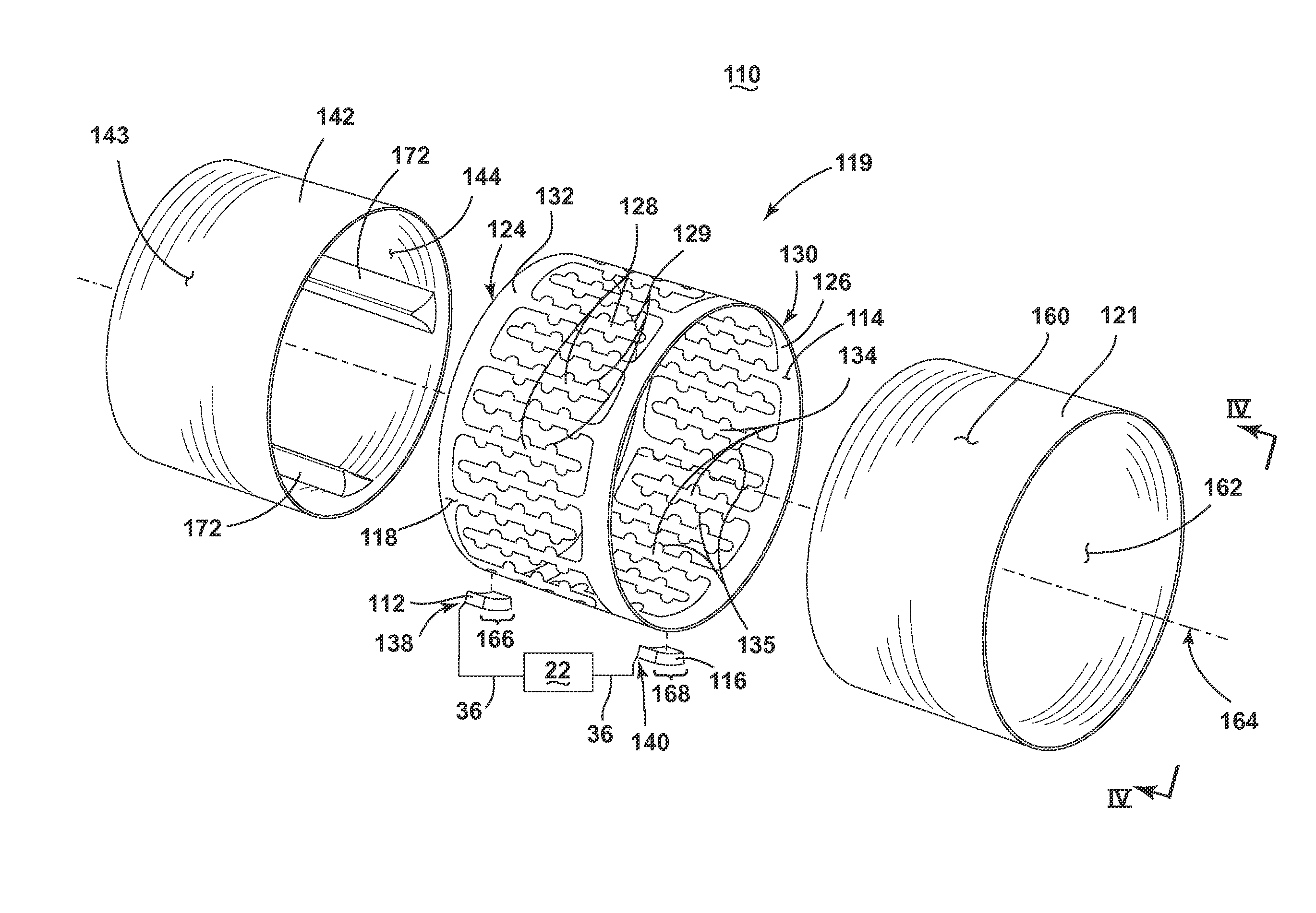
[0037]As shown in FIG. 4, the assembled laundry drying applicator 110, according to the invention, creates a substantially radial integration between the sleeve 142, second cathode and anode elements 114, 118 (cathode element not shown), and drum 119 elements. It may be envisioned that additional layers may be interleaved between the illustrated elements. Additionally, while the anode ring 112 and cathode ring 116 are shown offset about the rotational axis for illustrative purposes, alternate placement of each ring 112, 116 may be envisioned.
[0038]The second embodiment of the laundry drying applicator 110 operates by creating a first capacitive coupling between the anode ring 112 and the second anode element 118 separated by at least a portion of the drum 119, a second capacitive coupling between the cathode ring 116 and the second cathode element 114 separated by at least a portion of the drum 119, and a third capacitive coupling between the pluralities of teeth 128, 134 and the pl...
fourth embodiment
[0048]the laundry drying applicator 310 operates by creating a first capacitive coupling between the anode ring 312 and the second anode element 118 separated by at least a portion of the drum 319 or air gap, a second capacitive coupling between the cathode ring 316 and the second cathode element 114 separated by at least a portion of the drum 319 or air gap. During rotation, the RF generator 22 may be off, or may be continuously, selectively, automatically, or intermittently energized to generate an e-field between the first, second, and third capacitive couplings which interacts with liquid in the laundry. The liquid interacting with the e-field located within the inner surface 144 will be dielectrically heated to effect a drying of the laundry.
[0049]In another envisioned configuration, the anode ring 312 is directly connected to the second anode element 118 and the cathode ring 316 is directly connected to the second cathode element 114. In this configuration, only a single capac...
PUM
 Abstract
Description
Claims
Application Information