Organic light-emitting device incorporating a triplet-triplet annihilation promoter and method of forming the same
a light-emitting device and promoter technology, applied in the direction of organic semiconductor devices, luminescent compositions, chemistry apparatus and processes, etc., can solve the problem of significant redshift in the emission spectrum, achieve small increase in device lifetime, prevent or reduce triplet-triplet or triplet-singlet interactions, and improve the effect of lifetim
- Summary
- Abstract
- Description
- Claims
- Application Information
AI Technical Summary
Benefits of technology
Problems solved by technology
Method used
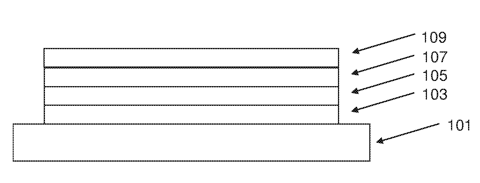
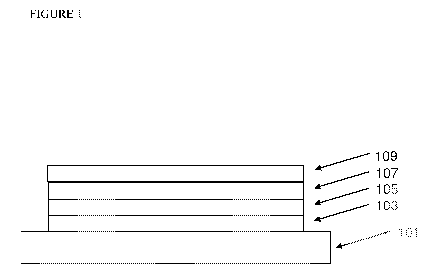
Image

Examples
example 1
Device Example 1
[0261]A device was prepared as described according to the General Device Process wherein the blue light-emitting polymer was Blue Light-Emitting Polymer 1, and wherein the Blue Light-Emitting Polymer 1:TTA Promoter Polymer 1 molar ratio was 99:1.
[0262]Comparative Device 1
[0263]A device was prepared according to Device Example 1 except that the blue light-emitting layer was formed by spin-coating Blue Light-Emitting Polymer 1 only, without TTA Promoter Polymer 1.
[0264]With reference to FIG. 4, the intensity of blue emission relative to red emission is much greater in Device Example 1 than in Comparative Device 1. Relative intensity of green emission is also higher.
[0265]With reference to Table 1, both CIE x and y co-ordinate values of Device Example 1 are lower than those of Comparative Device 1, and closer to “pure” white emission having co-ordinates of (0.33, 0.33); the colour rendering index is higher; the correlated colour temperature is higher; and the Duv distan...
example 2
Device Example 2
[0271]A device was prepared as described according to the General Device Process wherein the blue light-emitting polymer was Blue Light-Emitting Polymer 2, and wherein the Blue Light-Emitting Polymer 2:TTA Promoter Polymer 1 molar ratio was 99:1.
[0272]Comparative Device 2
[0273]A device was prepared according to Device Example 2 except that the blue light-emitting layer was formed by spin-coating Blue Light-Emitting Polymer 2 only, without TTA Promoter Polymer 1.
[0274]With reference to FIG. 8, the intensity of blue emission relative to red emission is much greater in Device Example 2 than in Comparative Device 2. Relative intensity of green emission is also higher.
[0275]With reference to Table 2, both CIE x and y co-ordinate values of Device Example 1 are lower than those of Comparative Device 1, and closer to “pure” white emission having co-ordinates of (0.33, 0.33); the colour rendering index is higher; and the correlated colour temperature is higher.
[0276]
TABLE 2Co...
example 3
Device Example 3
[0279]A device was prepared as described in Device Example 2 except that the Blue Light-Emitting Polymer 2:TTA Promoter Polymer 1 molar ratio was 98:2.
PUM
| Property | Measurement | Unit |
|---|---|---|
| temperature | aaaaa | aaaaa |
| temperature | aaaaa | aaaaa |
| thickness | aaaaa | aaaaa |
Abstract
Description
Claims
Application Information
 - R&D
- Intellectual Property
- Life Sciences
- Materials
- Tech Scout
- Unparalleled Data Quality
- Higher Quality Content
- 60% Fewer Hallucinations
Browse by: Latest US Patents, China's latest patents, Technical Efficacy Thesaurus, Application Domain, Technology Topic, Popular Technical Reports.
© 2025 PatSnap. All rights reserved.Legal|Privacy policy|Modern Slavery Act Transparency Statement|Sitemap|About US| Contact US: help@patsnap.com