Power generation unit of integrated gearbox design for aircraft engine

a technology of power generation unit and aircraft engine, which is applied in the direction of engine starters, machines/engines, mechanical equipment, etc., can solve the problems of increasing the size of the power generation unit, suppressing the unsatisfactory increase of the frontal projected area, and achieving large power generating capacity. , the effect of easy re-driving

Active Publication Date: 2017-01-17
KAWASAKI HEAVY IND LTD
View PDF68 Cites 11 Cited by
  • Summary
  • Abstract
  • Description
  • Claims
  • Application Information

AI Technical Summary

Benefits of technology

[0007]The aircraft engine is required to have a frontal projected area of the contour reduced as small as possible to thereby reduce the air resistance in order to increase the mileage and also to have a compact profile in order to increase the stealth performance. With respect to the power generation unit, which is the biggest auxiliary equipment of all used in an aircraft, a power generating capacity of about 90 kVA was required for the aircraft having a 200 seating capacity used in 1980s, but for the aircraft in these recent years, say, 2010s, a power generating capacity of 250 kVA or higher has been required the aircrafts have been remarkably more electric. If such a large power generating capacity of 250 kVA or higher is desired to be taken out from the coil exciting type electric power generator, which is employed in the existing power generation unit, the coil turns of the rotor and the stator need to be increased to a value required to secure the desired large power generating capacity. The increase in coil turns leads to the use of the rotor and the stator each having an increased outer diameter, resulting in increasing the size of the power generation unit. Also, the accessory gearbox used to support the large power generation unit discussed above with respect to the engine is necessarily increased in size. Thus, the increase in size of the power generation unit and the accessory gearbox appears to be disincentive to the improvements in mileage and stealth performance that are planned through the reduction of the frontal projected area of the aircraft engine.

Problems solved by technology

The increase in coil turns leads to the use of the rotor and the stator each having an increased outer diameter, resulting in increasing the size of the power generation unit.

Method used


Image

  • Power generation unit of integrated gearbox design for aircraft engine
  • Power generation unit of integrated gearbox design for aircraft engine
  • Power generation unit of integrated gearbox design for aircraft engine

Examples


Embodiment Construction

[0030]Hereinafter, embodiments of the present invention will be described in detail with particular reference to the accompanying drawings.

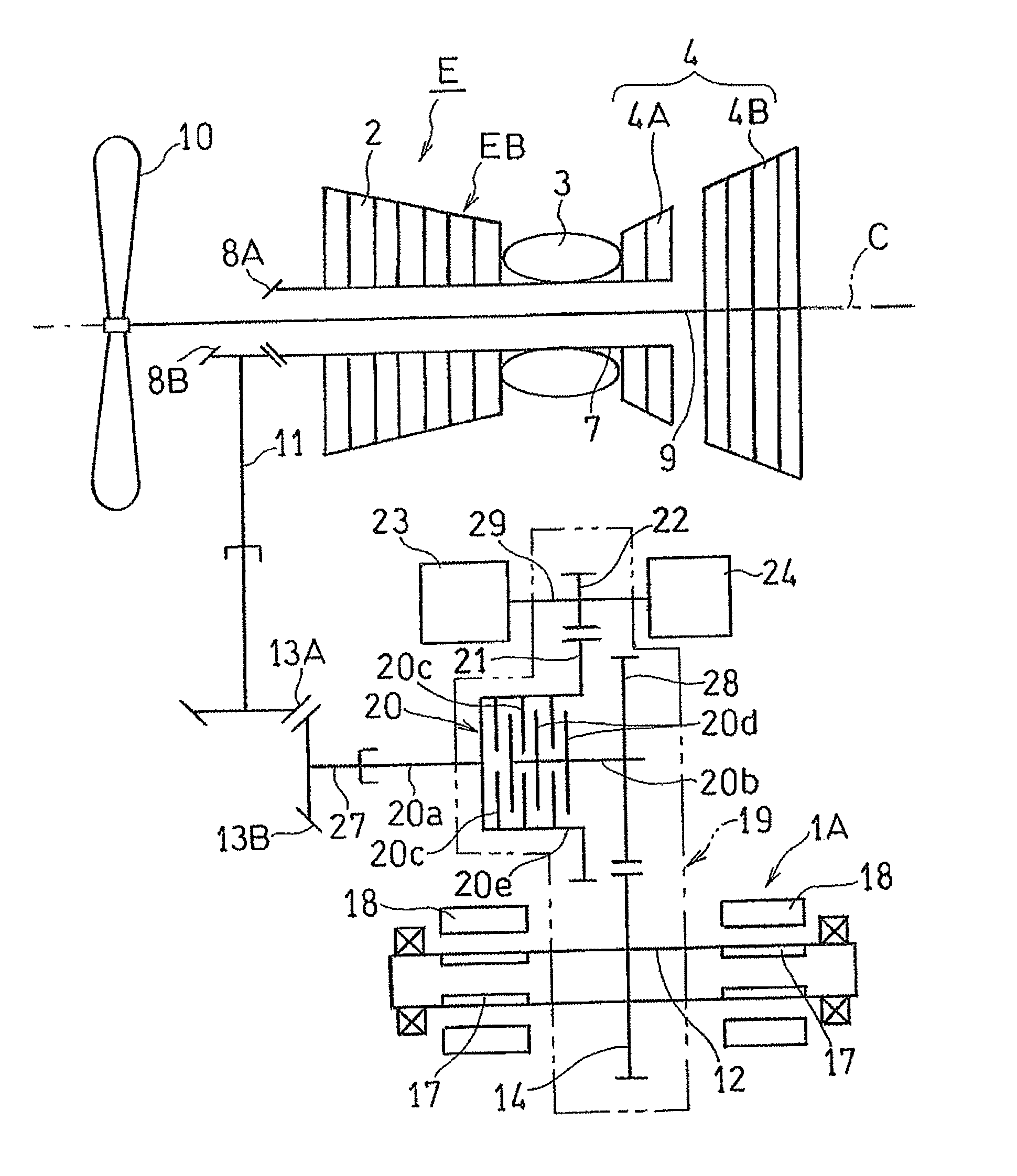
[0031]FIG. 1 schematically shows the manner of connection of the power generation unit 1A, designed according to the first embodiment, with an engine main body EB of the aircraft engine E. As shown therein, the engine E is a turbofan engine of biaxial type and includes, as components, a compressor 2, a combustor 3, a turbine 4 and a fan 10. Fuel is mixed with a compressed air, which is supplied from the compressor 2 and is then burned by the combustor 3 to produce a high temperature and high pressure combustion gas as a result of the combustion of the air-fuel mixture, which gas is subsequently supplied to the turbine 4. The turbine 4 includes a high pressure turbine 4A on a front stage side and a low pressure turbine 4B on a rear stage side. The compressor 2 is drivingly connected with the high pressure turbine 4A through a hollow high pressure ...


PUM


Abstract

A power generation unit is connected with an engine rotary shaft via an accessory gearbox. A rotor extends through the accessory gearbox and a drive gear is disposed at an intermediate portion of the rotor for driving the latter. Permanent magnet elements are mounted on opposite side portions with the intermediate portion intervening therebetween, and stator coils are disposed so as to confront respective outer peripheries of the permanent magnet elements.

Description

CROSS REFERENCE TO THE RELATED APPLICATION[0001]This application is a continuation application, under 35 U.S.C. §111(a), of international application No. PCT / JP2013 / 064241, filed May 22, 2013, which claims priority to Japanese patent application No. 2012-122579, filed May 30, 2012, the disclosure of which are incorporated by reference in their entirety into this application.BACKGROUND OF THE INVENTION[0002]Field of the Invention[0003]The present invention relates to an electric power generator of an integrated gear box design, which is fitted to an aircraft engine and driven by an engine rotary shaft.[0004]Description of Related Art[0005]The aircraft engine has various aircraft accessory equipments such as, for example, an power generating unit, a starter, a hydraulic pump, a lubrication pump and a fuel pump, which are fitted to an engine main body through an accessory gear box (AGB) so that they can be driven by an engine rotary shaft through the accessory gearbox. For the power ge...

Claims


Application Information

Patent Timeline
Patent Type & Authority Patents(United States)
IPC IPC(8): F02B63/04H02K7/18F02C7/32H02K7/10H02K7/116H02K7/108F02C7/268F02N11/04F01D15/10F01D15/12
CPCH02K7/1807F02C7/268F02C7/32F02N11/04H02K7/108H02K7/116H02K7/1823F01D15/10F01D15/12F05D2220/768F05D2260/85
Inventor GOI, TATSUHIKOTANAKA, KENICHIRO
Owner KAWASAKI HEAVY IND LTD
Why Eureka
Try Eureka