
High-frequency generator

Active Publication Date: 2017-01-17
COMMISSARIAT A LENERGIE ATOMIQUE ET AUX ENERGIES ALTERNATIVES
View PDF10 Cites 2 Cited by
  • Summary
  • Abstract
  • Description
  • Claims
  • Application Information

AI Technical Summary

Benefits of technology

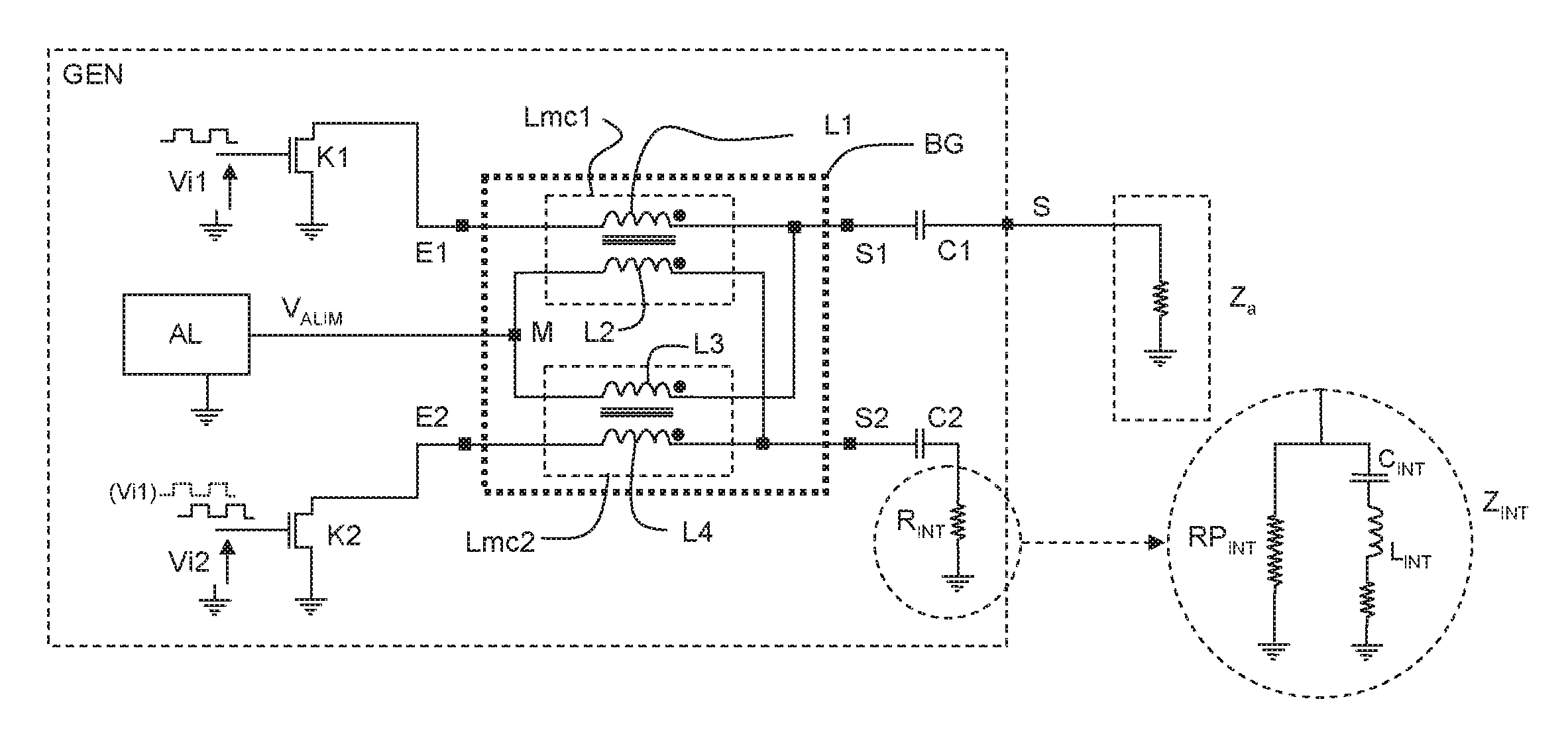
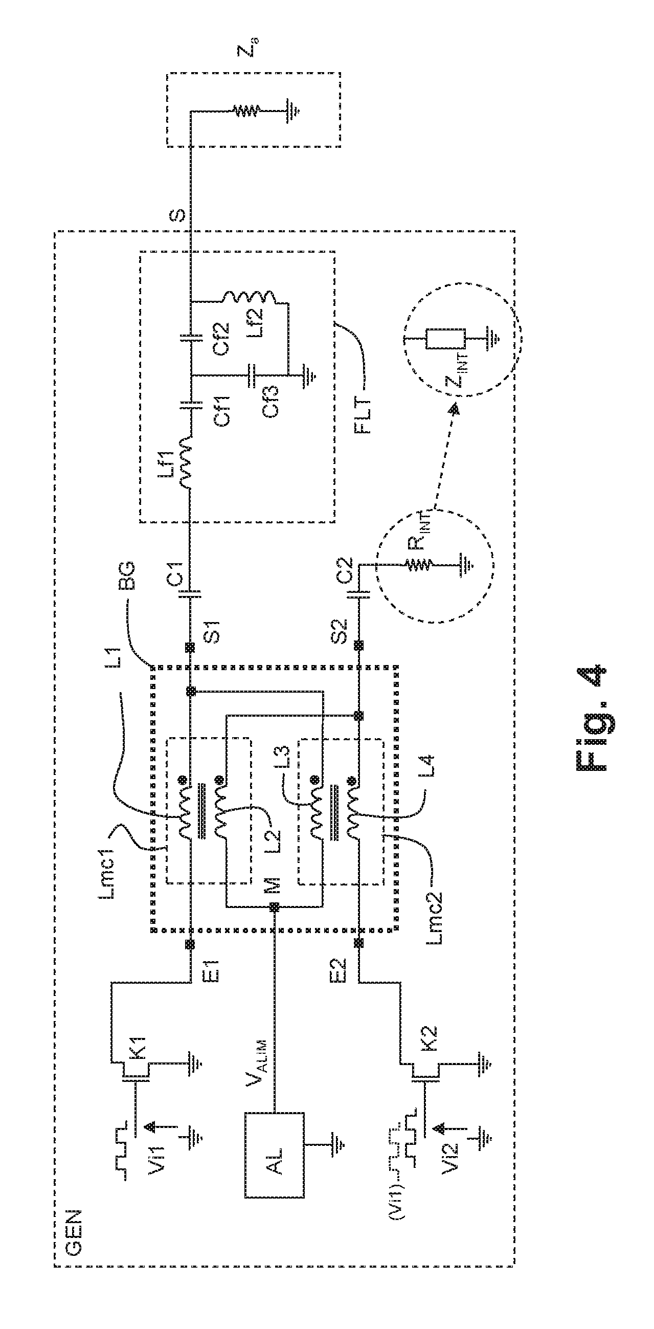
This patent proposes a new diagram for an output stage of a high-frequency generator that is simple and effective. The diagram allows for the selection of the internal impedance of the output stage. The use of common-mode inductors, which are preferential, makes it easy to obtain components at a reduced cost. These inductors can have a wide range of inductance values, which is not critical for assembly. A decoupling capacitor can be used to avoid disrupting the power supply with transient voltages or currents arising from the current commutations in the inductive lines. A band-pass filter is used to eliminate harmonics and allow the activation frequency of the switches to pass through.

Problems solved by technology

The reason for this is that it is desirable that the transistors have the same characteristics; now, it is difficult to obtain very similar characteristics, in terms of impedance or recovery time at the moment of switching, if the transistors are not of the same type.
Additionally, the circuit diagrams are more complex if transistors of different types are used, especially for the control functions of the latter, above all if a variable supply voltage must be used, which is sometimes necessary to ensure a variable output power.
However, a double-wound transformer is expensive as its characteristics must imperatively be adapted to a given application and thus such a component is not readily commercially available.
They have drawbacks and notably the fact that a DC component of high value can flow in each common-mode inductor, risking the saturation of the magnetic cores.
Additionally, these diagrams do not make it possible to adjust an internal impedance value of the output stage of the generator, whereas it is sometimes desirable to be able to choose the internal impedance value so as to match it to the load located downstream of the generator.

Method used


Image

  • High-frequency generator
  • High-frequency generator
  • High-frequency generator

Examples


Embodiment Construction

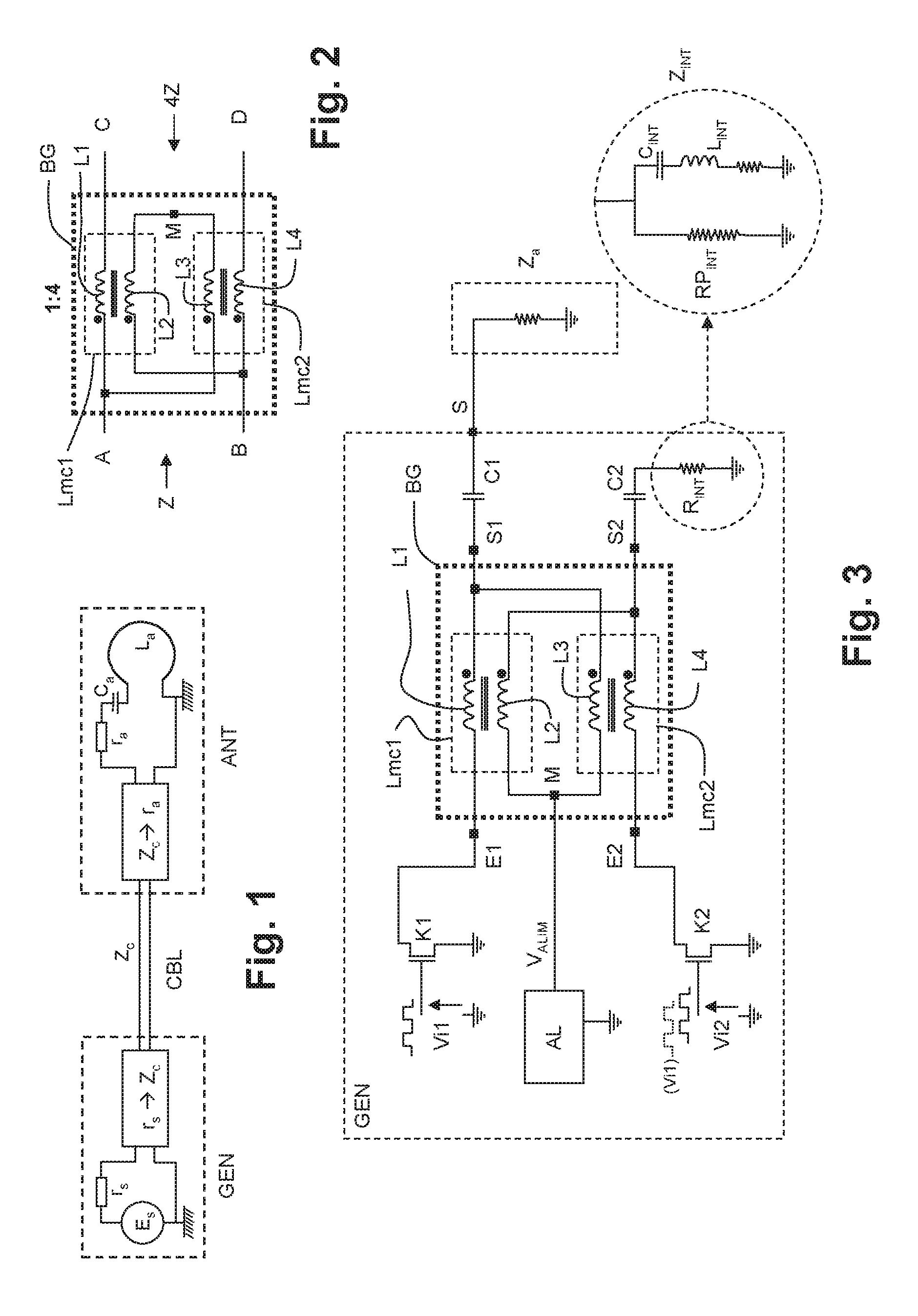
[0036]In FIG. 1, the basic composition of the emitting part of a base station in a high-frequency communication system is shown. In the following it is considered to be an identification system for RFID tags in which an exchange of data takes place between the base station and objects bearing tags. The invention is however not limited to this application: the invention can even be applied outside of any data exchange system, for example for a remote power supply by induction of electronic circuits without their own power supply, or to recharge a rechargeable battery of a stand-alone system via induction.

[0037]The emitting part of the base station comprises a high-frequency generator GEN and an inductive antenna ANT. The generator is symbolized by a voltage source Es supplying an alternating signal at a high frequency F, this signal being able to be modulated, for example in amplitude or in phase; this voltage source is accompanied by an impedance in series rs representing the intern...


PUM


Abstract

The power stage at the output of a high-frequency generates operates in class D and comprises a voltage supply and a common earth, a first and a second switch linked to the common earth and periodically switched on at a high frequency F; these switches are linked to two common-mode inductors connected in a Guanella balun. Each common-mode inductor comprises two inductive lines with strong mutual coupling. The first switch is linked to the input of the first inductive line but not to the second, third and fourth lines and the second switch is linked to the input of the fourth inductive line but not to the first, second and third lines, the output of the first inductive line is linked to an output of the generator, the output of the fourth inductive line is linked to an internal resistor, the inputs of the second and third inductive lines are linked to the supply voltage source, the output of the third inductive line is linked to the output of the first inductive line and the output of the second inductive line is linked to the output of the fourth inductive line.

Description

CROSS-REFERENCE TO RELATED APPLICATIONS[0001]This application is a National Stage of International patent application PCT / EP2014 / 061435, filed on Jun. 3, 2014, which claims priority to foreign French patent application No. FR 1355187, filed on Jun. 6, 2013, the disclosures of which are incorporated by reference in their entirety.FIELD OF THE INVENTION[0002]The invention relates to high-frequency generators, and more particularly to the power stage at the output of the generator.[0003]Although the invention is applicable to a variety of contexts and producible frequencies, it will be described with respect to an application to a reader of an identification system using RFID (“Radio Frequency Identification”) tags. In such an application, the reader comprises a signal generator which, connected to or associated with an antenna, makes it possible to produce radiofrequency electromagnetic signals, for example in the range of 3 to 30 MHz; these signals carry information, and are picked u...

Claims


Application Information

Patent Timeline
IPC IPC(8): H03F3/217H03F3/193H03F3/19
CPCH03F3/217H03F3/19H03F3/193H03F3/2178H03F2200/09H03F2200/451H03F2200/541
Inventor THOMAS, THIERRYJOSSELIN, VINCENT
Owner COMMISSARIAT A LENERGIE ATOMIQUE ET AUX ENERGIES ALTERNATIVES
Learn More