Interferometer for Fourier transform infrared spectrometry

a technology of infrared spectrometry and interferometer, which is applied in the direction of optical radiation measurement, instruments, measurement devices, etc., can solve the problems of many existing approaches to support and move the optical components, insufficient protection against unwanted motion of the spectrometer components, and insufficient interference with each other, so as to reduce reflection and transmission losses, efficiently transfer infrared radiation, and minimize conductivity. the effect of hea

Active Publication Date: 2017-01-31
METTLER TOLEDO AUTOCHEM
View PDF12 Cites 7 Cited by
  • Summary
  • Abstract
  • Description
  • Claims
  • Application Information

AI Technical Summary

Benefits of technology

[0010]A scanning interferometer may further include a compensator plate which is placed in the radiation path, normally downstream of the beam splitter and spaced from the latter with only a narrow gap. Compensator plates are well known in the art. Their function is to ensure that light traveling through either arm of the interferometer encounters the same thickness of refractive material and, more particularly, to equalize dispersion in the two arms, with the result of producing nearly symmetric interferograms that minimize phase errors as a source of photometric error.
[0038]The motor driving the reciprocating movement of the scanner assembly is preferably configured as a linear motor of the kind used in loudspeakers, wherein a cylindrical coil is arranged in a corresponding cylindrical gap of a permanent magnet assembly which includes a permanent magnet with one or more pole pieces of high-permeability material, often soft iron, serving to channel the magnetic flux. However, unlike the customary arrangement of a loudspeaker, the drive coil in the interferometer of the invention is installed in a stationary position on the body, while the permanent magnet is rigidly attached to the scanner assembly. As a preferred feature of the invention, the mass distribution of the scanner assembly with the retro-reflector and the permanent magnet is balanced relative to the pivotal axis of the reciprocating swivel movement of the scanner assembly. In essence, the mass of the permanent magnet and pole pieces thus serve to counterbalance the mass of the retro-reflector. This has the effect of substantially immunizing the interferometer against velocity variations caused by linear and torsional vibrations in all axes other than the single rotary scan axis.

Problems solved by technology

Upon return to the beam splitter, the first and second partial beams are recombined and thereby caused to optically interfere with each other.
In surveying the state of the art of interferometers, the applicants have observed that many existing approaches to supporting and moving the optical components, in particular the scan mechanism, provide insufficient protection against unwanted motions of the spectrometer components in the presence of extraneous disturbances including shock, vibration and temperature fluctuation.

Method used


Image

  • Interferometer for Fourier transform infrared spectrometry
  • Interferometer for Fourier transform infrared spectrometry
  • Interferometer for Fourier transform infrared spectrometry

Examples


Embodiment Construction

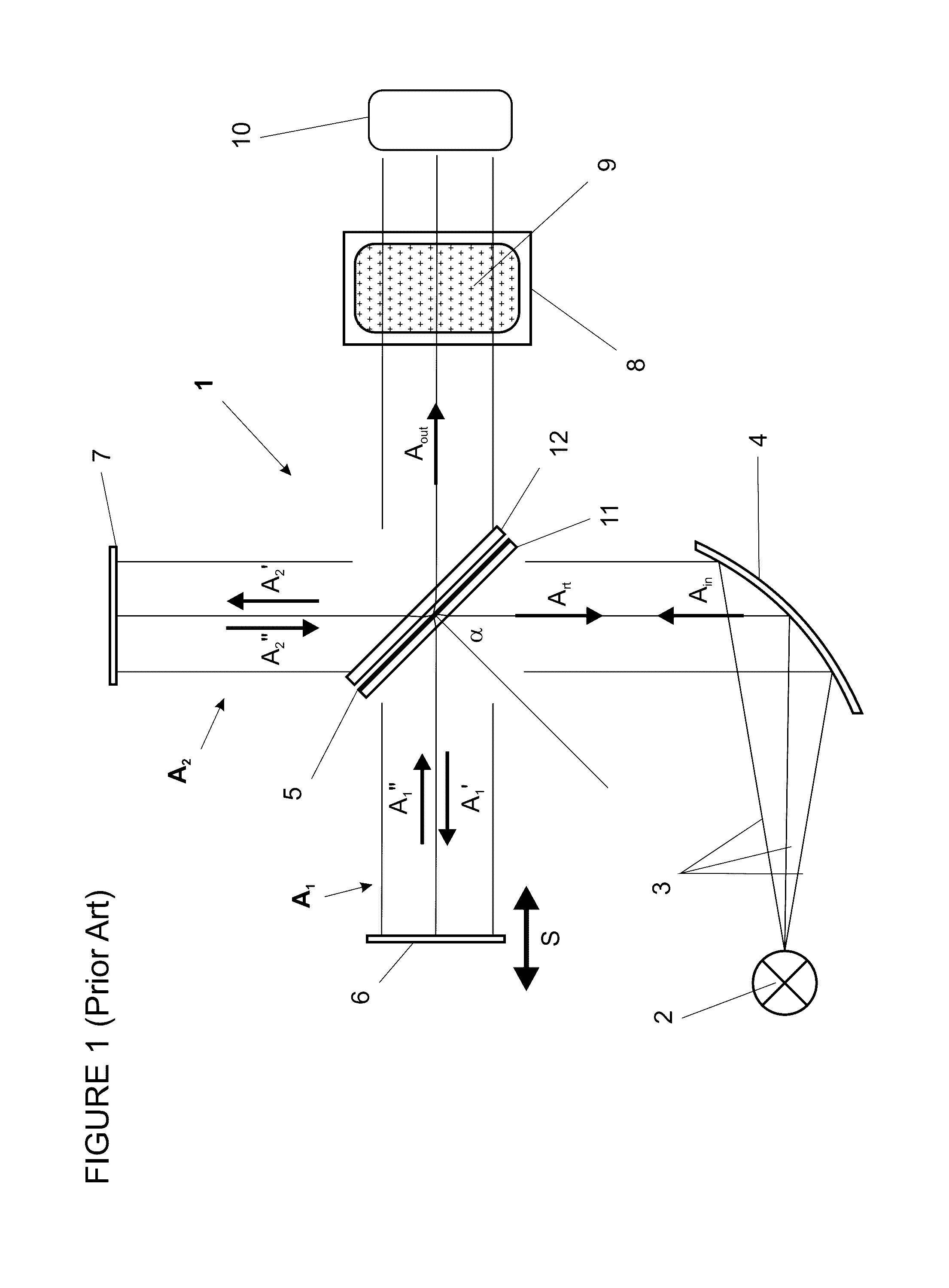
[0046]A scanning Michelson interferometer 1 as illustrated schematically in FIG. 1 includes a beam splitter 5 with a beam splitter coating 11, a compensator plate 12, a moving mirror 6 terminating a first arm A1 of the interferometer 1, and a fixed mirror 7 terminating a second arm A2 of the interferometer 1. The reciprocating scanning movement of the mirror 6 which causes a periodic variation in the length of the first arm A1 is indicated by the double arrow S. Radiation 3 from a source 2 is collimated by a collimating mirror 4 and directed to the beam splitter 5, which is positioned to receive the collimated incoming radiation Ain at an angle of incidence α of 45°. The beam splitter 5 divides the incoming radiation Ain into two partial beams propagating along the two arms A1 and A2, i.e. a first, reflected partial beam A1′ and a second, transmitted partial beam A2′ which propagate in directions 90° apart from each other to the two mirrors 6 and 7, respectively, where they are refl...


PUM


Abstract

An interferometer wherein an incident beam from a radiation source hits a beam splitter at a first oblique angle of incidence and is split into a first, reflected partial beam, and a second, transmitted partial beam, that subsequently travel along separate arms of the interferometer. The first and second partial beams are respectively intercepted, reflected, and re-split to form returning beam portions and reflected and transmitted exit beam portions. A second terminal mirror and a folding mirror, which intercepts the second partial beam at a second oblique angle of incidence, are associated with the second interferometer arm and positioned orthogonal to the reference plane and on opposite sides of the exit path, so that a section of the second partial beam from the folding mirror to the terminal mirror and back to the folding mirror crosses the exit beam twice.

Description

BACKGROUND AND SUMMARY[0001]The invention concerns interferometers for Fourier transform infrared (FT-IR) spectrometry, commonly referred to as FT-IR spectrometers. In the practice of FT-IR spectrometry, infrared radiation usually is brought into interaction with a sample, while the spectrum of the radiation, i.e. the intensity as a function of wavelength, is determined by using an interferometer to modulate each wavelength with a unique coding, then analysing the resulting signal by Fourier transformation. As the transmission and absorption of specific wavelengths of light are characteristic of molecular structure, number density and physicochemical environment, FT-IR spectroscopy can be used, for example, to identify unknown materials, to determine the purity or consistency of a sample, or to determine the components in a mixture as well as their respective proportions.[0002]One core element of almost all FT-IR spectrometers is a two-beam interferometer of the general type invente...

Claims


Application Information

Patent Timeline
Patent Type & Authority Patents(United States)
IPC IPC(8): G01J5/02G01J3/453G01J3/02G01J9/02
CPCG01J3/4535G01J3/453G01J3/0202G01J9/0215G01J3/4532G01J2003/4534
Inventor MANNING, CHRISTOPHERBLACKLIN, PETER ALFREDSHAH, NILESH
Owner METTLER TOLEDO AUTOCHEM
Why Eureka
Try Eureka