Integrated magnetics component

a technology of integrated magnetics and components, applied in the direction of transformers/inductance coils/windings/connections, inductance, electric variable regulation, etc., can solve the problems of multi-input power converters not being able to deliver power to the load at the same time, and achieve the reduction of the required number of variants, assembly costs, component costs, stock costs

Inactive Publication Date: 2017-02-14
DANMARKS TEKNISKE UNIV
View PDF10 Cites 3 Cited by
  • Summary
  • Abstract
  • Description
  • Claims
  • Application Information

AI Technical Summary

Benefits of technology

[0022]Preferably, each of the first and second inductor windings extend exclusively above the base member or above the top member in, or parallel to, the horizontal plane. In this embodiment, each of the first and second inductor winding possess a horizontally folded geometry or layout encircling the first pair of adjacent legs or encircling the second pair of adjacent legs as mentioned above. In this embodiment, the first and second input inductor windings possess a horizontally folded geometry or layout. A significant advantage of this embodiment is that the first and second input conductor windings can easily be integrated with standard types of stiff or flexible printed circuit boards (PCBs). Other components of the power converter can be integrated on the PCB together with the inductor windings such that effective modularization of the power converter is enabled.
[0035]adjusting a duty cycle of the first pulse width modulated drive signal and / or a duty cycle of the second pulse width modulated drive signal to adjust the DC output voltage. The ability to control the DC output voltage either by adjusting the duty cycle, adjusting the phase angle difference or adjusting both leads to an extremely flexible way of controlling the DC output voltage with numerous benefits such as the provision of wider input and / or output voltage ranges of the multiple-input isolated power converter. Consequently, the same isolated power converter can be readily adapted to a broad variety of applications and therefore reduces the required number of variants of a given power converter topology, lowering assembly costs, component costs, stock costs etc. The flexible adaptation offered by the present multiple-input isolated power converter is particularly well-suited for power conversion in connection with clean energy sources like photovoltaic cells which often output a wide range of different voltages.

Problems solved by technology

A common limitation of some known multiple-input power converters is that only one input power source is allowed to transfer power or energy to the output at a time to prevent power coupling effects.
Without these reverse-blocking diodes, different input sources coupled to the multi-input power converter cannot deliver power to the load simultaneously.
In addition, higher current stress in low side MOSFETs of the input driver can be imposed due to a clamped voltage of the mutually coupled input inductor windings which causes a higher power loss.

Method used


Image

  • Integrated magnetics component
  • Integrated magnetics component
  • Integrated magnetics component

Examples


first embodiment

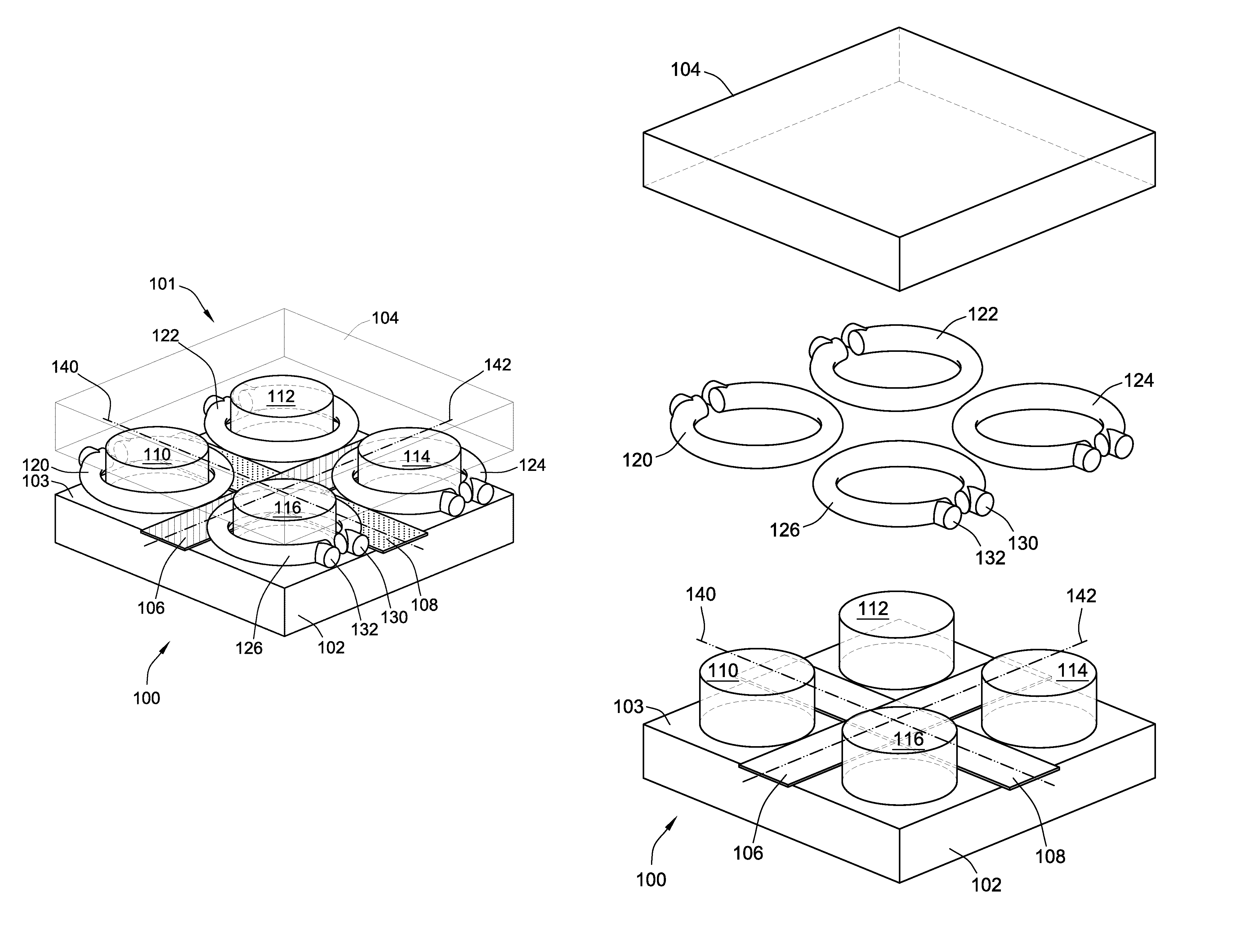
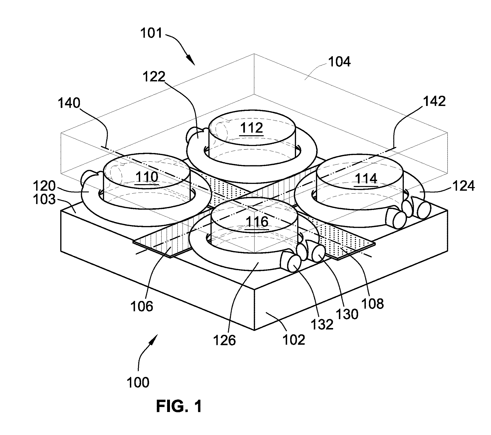
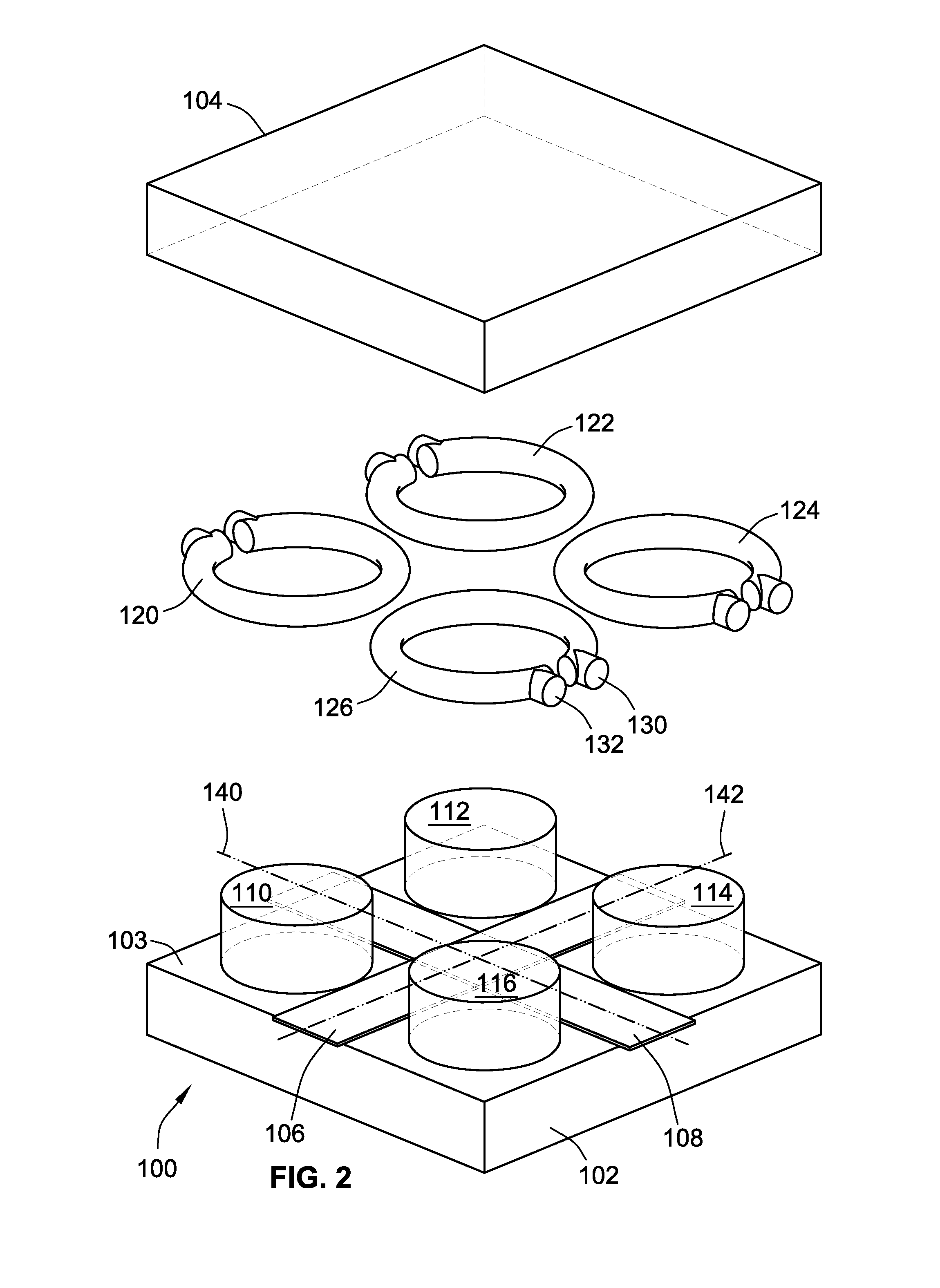
[0051]FIG. 1 shows an assembled perspective view of an integrated magnetics component 100 in accordance with the invention. The integrated magnetics component 100 comprises a magnetically permeable core 101 comprising a base member 102 and a top member 104. The base member 102 comprises a first leg 110, a second leg 112, a third leg 114 and fourth leg 116 all protruding substantially perpendicularly from the base member 102 to a lower surface of the top member such that the top member is attached to opposite ends of the first, second, third and fourth legs, 110, 112,114 and 116, respectively, relative to the base member 102. The attachment between the opposite ends of the first, second, third and fourth legs, 110, 112,114 and 116, respectively, and the top member may be provided in numerous ways such as by soldering, gluing, welding, press-fitting and the attachment mechanism preferably ensures good magnetic coupling between the top member 104 and each of the legs 110, 112,114 and 1...

second embodiment

[0068]In the integrated magnetics component 500, a first input conductor forms part of a first inductor winding 506 which is formed as a single full turn winding. The first inductor winding 506 comprises a flat ribbon or strip of conductive material. However, instead of the U-shaped form used for the first inductor winding 506 in the invention, the present first inductor winding 506 is folded in a horizontal plane extending along the upper surface 503 of the flat quadratic structure of a base member 502. In this manner, the first input inductor winding 506 extends exclusively above the base member 502 in the horizontal plane. However, the first input conductor is a straight flat strip of conductive material which forms a first leg or segment of the first inductor winding 506 and extends in-between the first, second, third and fourth legs, 510, 512, 514 and 516, respectively, of the integrated magnetics component 500 in a manner similar to the above discussed previous embodiments of ...

third embodiment

[0071]FIG. 6 is an exploded perspective view of the integrated magnetics component 500 depicted above in accordance with the invention. The horizontally folded layouts or geometries of the first and second inductor windings 506, 508 are evident such that the inductor windings are formed by respective flat folded strips of electrical conductors. Likewise, the figure depicts the orthogonal orientation in the horizontal plane of the first conductor axis 542, associated with the first input conductor 506, relative to the second coil axis 540, associated with the second input conductor 508.

[0072]FIG. 7a) illustrates respective magnetic flux directions through the first, second, third and fourth legs, 110, 112, 114 and 116, respectively, of the integrated magnetics component 100 in accordance with the first embodiment of the invention in a first input current state of four different input current states. The skilled person will appreciate that the respective magnetic flux directions throu...


PUM

PropertyMeasurementUnit
phase angleaaaaaaaaaa

Abstract

The present invention relates to an integrated magnetics component comprising a magnetically permeable core comprising a base member extending in a horizontal plane and first, second, third and fourth legs protruding substantially perpendicularly from the base member. First, second, third and fourth output inductor windings are wound around the first, second, third and fourth legs, respectively. A first input conductor of the integrated magnetics component has a first conductor axis and extends in-between the first, second, third and fourth legs to induce a first magnetic flux through a first flux path of the magnetically permeable core. A second input conductor of the integrated magnetics component has a second coil axis extending substantially perpendicularly to the first conductor axis to induce a second magnetic flux through a second flux path of the magnetically permeable core extending substantially orthogonally to the first flux path. Another aspect of the invention relates to a multiple-input isolated power converter comprising the integrated magnetics component.

Description

[0001]The present invention relates to an integrated magnetics component comprising a magnetically permeable core comprising a base member extending in a horizontal plane and first, second, third and fourth legs protruding substantially perpendicularly from the base member. First, second, third and fourth output inductor windings are wound around the first, second, third and fourth legs, respectively. A first input conductor of the integrated magnetics component has a first coil axis and extends in-between the first, second, third and fourth legs to induce a first magnetic flux through a first flux path of the magnetically permeable core. A second input conductor of the integrated magnetics component has a second coil axis extending substantially perpendicularly to the first coil axis to induce a second magnetic flux through a second flux path of the magnetically permeable core extending substantially orthogonally to the first flux path. Another aspect of the invention relates to a ...

Claims


Application Information

Patent Timeline
Patent Type & Authority Patents(United States)
IPC IPC(8): H01F27/28H01F30/06H02M3/335H01F38/00H01L49/02H02M3/28H02M1/00
CPCH01L28/10H01F27/28H01F30/06H01F38/00H02M3/335H02M3/33546H02M3/285H02M2001/0064H01F27/38H02M1/0064
Inventor OUYANG, ZIWEIANDERSEN, MICHAEL A. E.ZHANG, ZHE
Owner DANMARKS TEKNISKE UNIV
Why Eureka
Try Eureka