Fixing member and manufacturing method therefor, fixing device, and image forming apparatus

a manufacturing method and technology of fixing parts, applied in the direction of instruments, electrographic processes, synthetic resin layered products, etc., can solve the problems of insufficient enhancement of difficult to adopt fep, poor toner releasability of the surface layer, etc., to achieve excellent toner releasability, stable formation of high-quality electrophotographic images, and high abrasion resistance

Active Publication Date: 2017-02-21
CANON KK
View PDF28 Cites 1 Cited by
  • Summary
  • Abstract
  • Description
  • Claims
  • Application Information

AI Technical Summary

Benefits of technology

[0016]Further, the present invention is directed to providing a fixing device and an image forming apparatus that contribute to the stable formation of a high-quality electrophotographic image.
[0027]According to one embodiment of the present invention, the low-cost fixing member having high abrasion resistance and being excellent in toner releasability can be provided. Further, according to other embodiments of the present invention, the fixing device and the image forming apparatus that contribute to the stable formation of a high-quality electrophotographic image can be provided.

Problems solved by technology

In addition, the toner releasability of the FEP is relatively inferior to those of the PTFE and the PFA.
For those reasons, it can be said that the FEP is a material that is difficult to adopt as the surface layer of the fixing member.
As a result, although the abrasion resistance of the surface layer was certainly improved, the toner releasability of the surface of the surface layer was not enhanced to a satisfactory level.

Method used

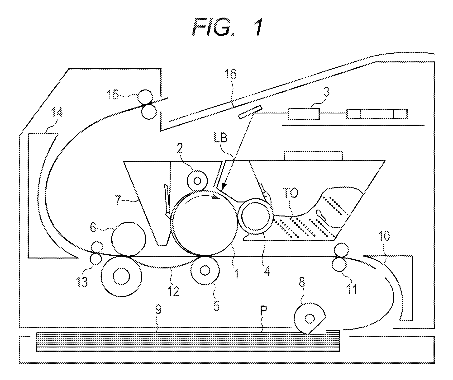
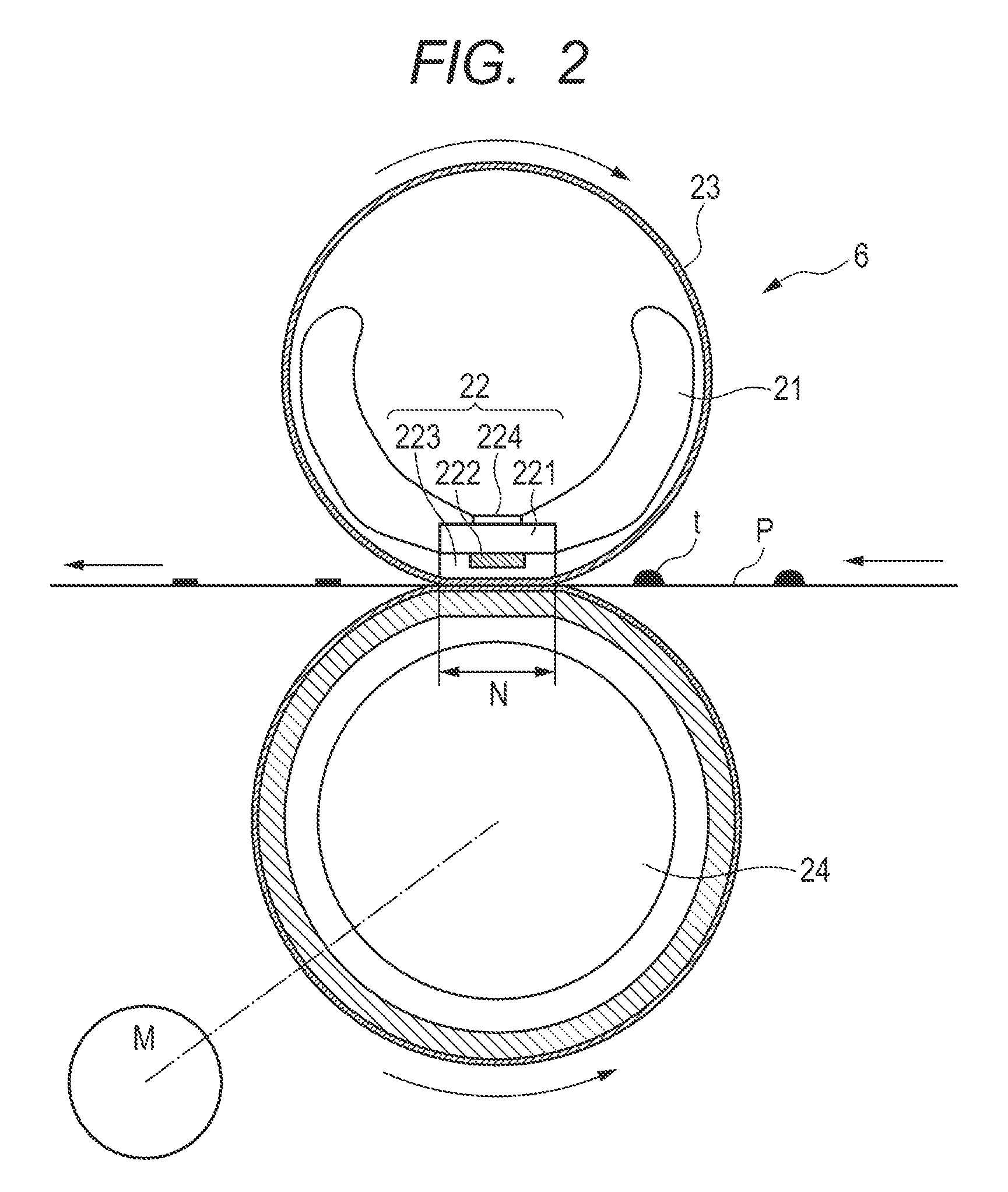
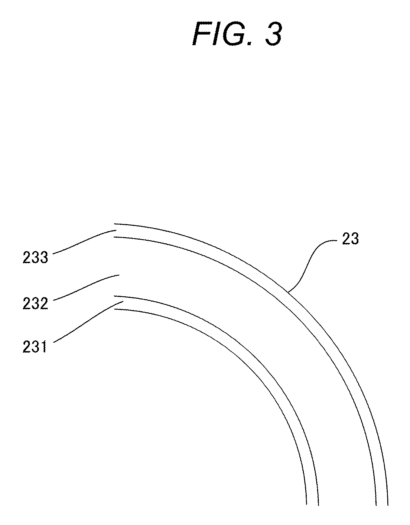

Image

  • Fixing member and manufacturing method therefor, fixing device, and image forming apparatus
  • Fixing member and manufacturing method therefor, fixing device, and image forming apparatus
  • Fixing member and manufacturing method therefor, fixing device, and image forming apparatus

Examples


example 1

[0103]As a base member for a fixing belt serving as a fixing member according to the present invention, a stainless-steel film having an outer diameter of 30 mm, a thickness of 40 μm, and an axial length of 400 mm was prepared.

[0104]A liquid silicone rubber mixture containing an addition curable silicone rubber (trade name: XE15-B9236, manufactured by Momentive Performance Materials Japan LLC) was applied onto the stainless-steel film through use of a ring-shaped coating head, to thereby form a coating film of the liquid silicone rubber mixture. The coating film had a thickness of 300 μm. Then, the coating film was heated to 200° C. so as to react the addition curable silicone rubber in the coating film, and thus an elastic layer containing silicone rubber was formed.

[0105]Next, a surface of the elastic layer was treated with excimer UV light, and thereafter a primer (trade name: EK-1909S21L, manufactured by Daikin Industries, Ltd.) was uniformly applied onto the surface to a thickn...

example 2

[0135]A fixing belt was produced in the same way as in Example 1 except for setting the temperature of the film of the uncrosslinked FEP resin to 90° C. at a time of irradiation with an electron beam and subjected to Evaluations 1 to 5.

example 3

[0136]A fixing belt was produced in the same way as in Example 1 except for setting the temperature of the film of the uncrosslinked FEP resin to 180° C. at a time of irradiation with an electron beam and subjected to Evaluations 1 to 5.


PUM

PropertyMeasurementUnit
wetting tensionaaaaaaaaaa
contact angleaaaaaaaaaa
temperatureaaaaaaaaaa

Abstract

The present invention relates to a fixing member having high abrasion resistance and being excellent in toner releasability, and a method of manufacturing the fixing member. The fixing member according to the present invention includes: a base member; an elastic layer formed on a surface of the base member; and a surface layer, in which the surface layer contains a tetrafluoroethylene-hexafluoropropylene copolymer having a specific partial structure and has a surface that forms a contact angle of 65° or more with respect to a wetting tension test mixture having a wetting tension of 31.0 mN / m.

Description

CROSS-REFERENCE TO RELATED APPLICATIONS[0001]This application is a continuation of International Application No. PCT / JP2015 / 000226, filed Jan. 20, 2015, which claims the benefit of Japanese Patent Application No. 2014-020349, filed Feb. 5, 2014.BACKGROUND OF THE INVENTION[0002]Field of the Invention[0003]The present invention relates to a fixing member to be used in a heat-fixing device of an electrophotographic image forming apparatus, a method of manufacturing the fixing member, a fixing device, and to an image forming apparatus.[0004]Description of the Related Art[0005]As a fixing member to be used in a heat-fixing device of an electrophotographic image forming apparatus such as a printer, a copying machine, or a fax machine, there is given a fixing member having a film shape or a roller shape. As such fixing member, there has been known a fixing member that includes a film-shaped or roller-shaped base member made of a heat-resistant resin or a metal, an elastic layer made of a h...

Claims


Application Information

Patent Timeline
Patent Type & Authority Patents(United States)
IPC IPC(8): G03G15/20C08J7/12B32B15/18B32B25/20B32B25/08B32B27/16B32B15/06B32B27/28B32B27/32B32B1/08
CPCG03G15/206B32B1/08B32B15/06B32B15/18B32B25/08B32B25/20B32B27/16B32B27/281B32B27/322G03G15/20B32B2307/306B32B2307/51B32B2307/554G03G15/2057
Inventor OSHIMA, YOSHIHITOMAEDA, MATSUTAKA
Owner CANON KK
Why Eureka
Try Eureka