Multi-stage flyback converter for wide input voltage range applications

a converter and input voltage technology, applied in the field of switching power converters, can solve the problems of high voltage rating components prohibitively expensive and difficult to obtain, and high voltage mosfets, such as those having an 800v rating, to solve the problem of high voltage stress and inefficiency

Inactive Publication Date: 2017-02-21
UNIVERSAL LIGHTING TECHNOLOGIES
View PDF8 Cites 13 Cited by
  • Summary
  • Abstract
  • Description
  • Claims
  • Application Information

AI Technical Summary

Benefits of technology

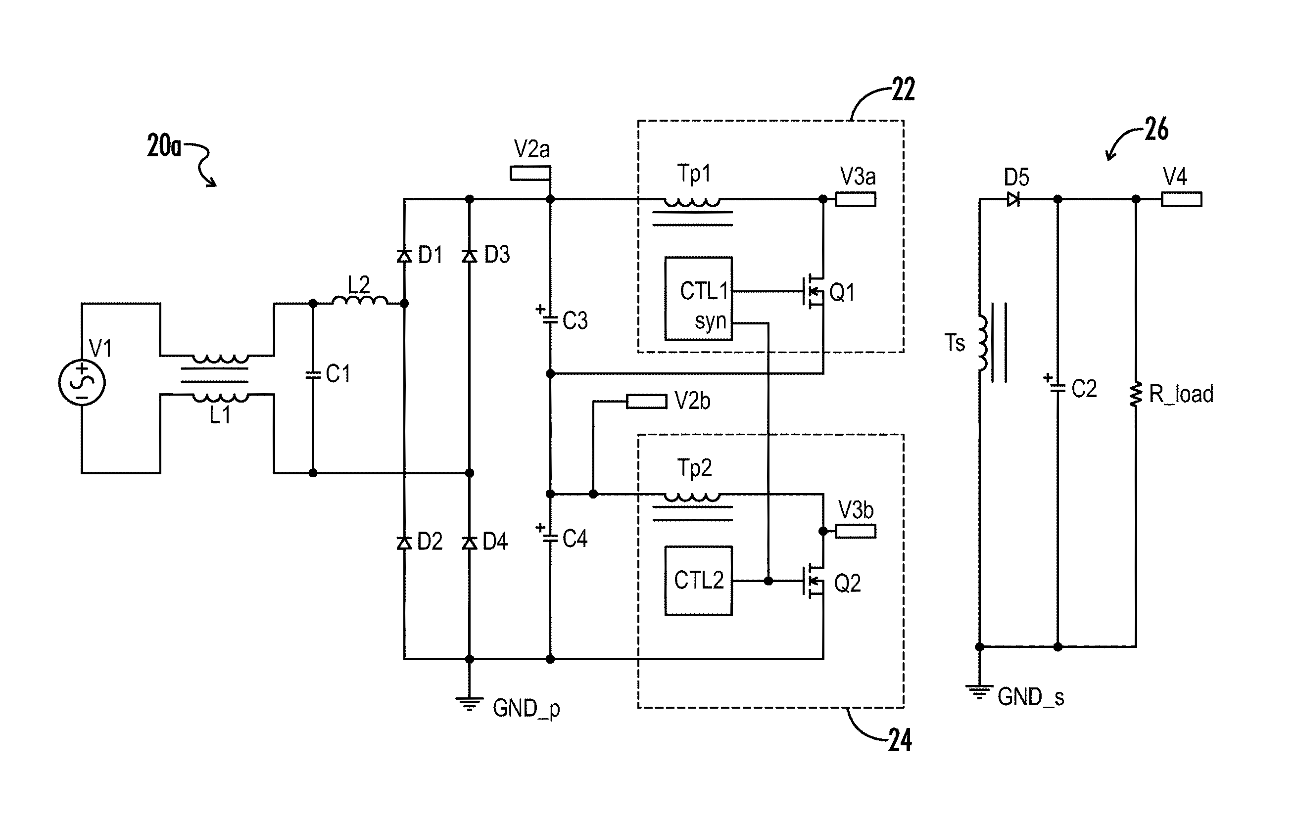
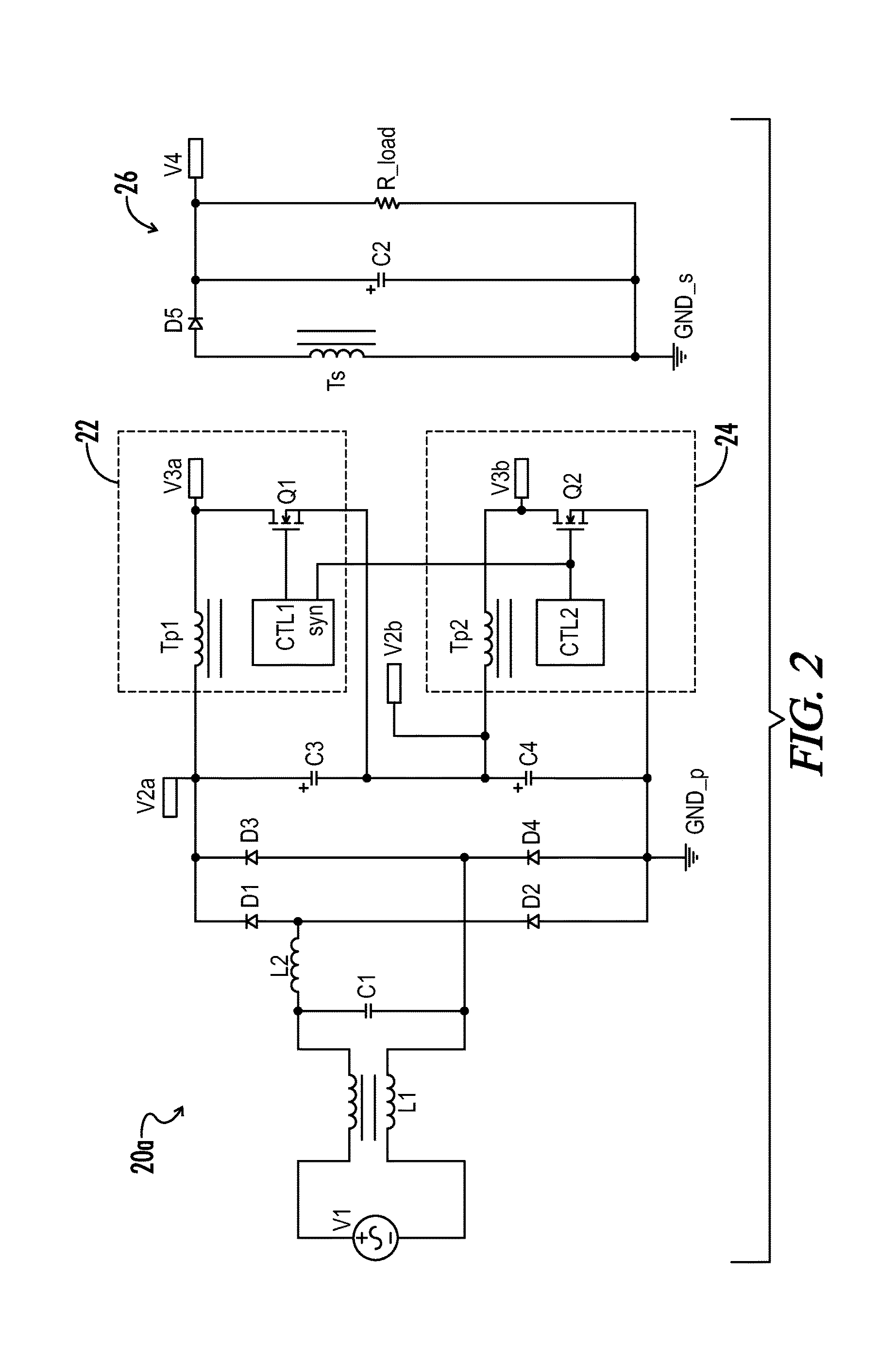
[0012]Various embodiments of a multi-stage topology according to the present invention may effectively solve the high voltage stress and inefficiency issues as previously noted with respect to conventional flyback power converters.

Problems solved by technology

This high voltage rating component, typically a MOSFET, is prohibitively expensive and can be difficult to obtain.
However, high voltage MOSFETs, such as for example those having an 800V rating, are expensive and difficult to obtain.
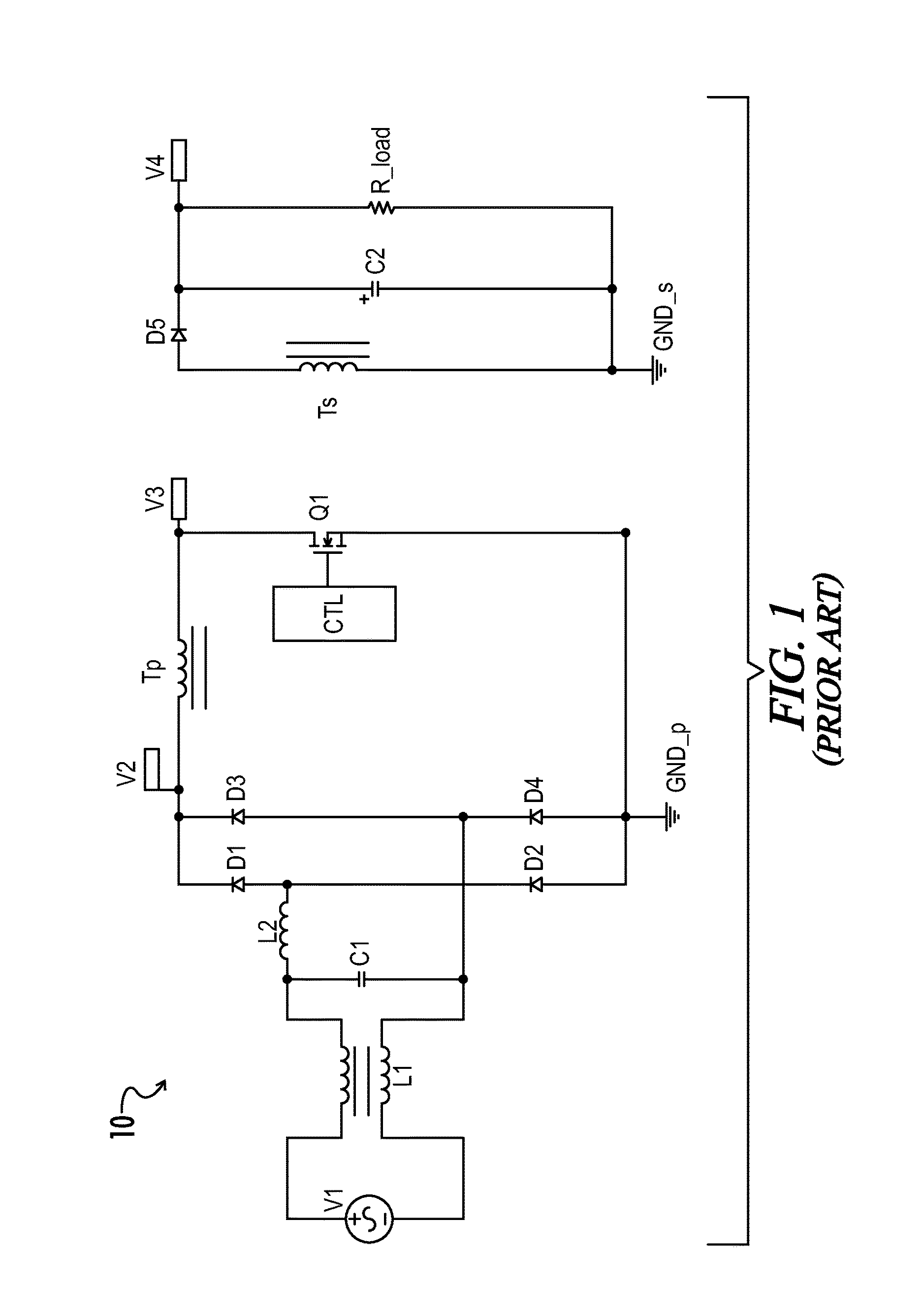
Briefly stated, if a conventional flyback topology is used for wide range input power factor correction (PFC) and DC-to-DC conversion applications, it is typically going to be prohibitively expensive and inefficient.

Method used


Image

  • Multi-stage flyback converter for wide input voltage range applications
  • Multi-stage flyback converter for wide input voltage range applications
  • Multi-stage flyback converter for wide input voltage range applications

Examples


Embodiment Construction

[0022]Throughout the specification and claims, the following terms take at least the meanings explicitly associated herein, unless the context dictates otherwise. The meanings identified below do not necessarily limit the terms, but merely provide illustrative examples for the terms.

[0023]The meaning of “a,”“an,” and “the” may include plural references, and the meaning of “in” may include “in” and “on.” The phrase “in one embodiment,” as used herein does not necessarily refer to the same embodiment, although it may. Conditional language used herein, such as, among others, “can,”“might,”“may,”“e.g.,” and the like, unless specifically stated otherwise, or otherwise understood within the context as used, is generally intended to convey that certain embodiments include, while other embodiments do not include, certain features, elements and / or states. Thus, such conditional language is not generally intended to imply that features, elements and / or states are in any way required for one o...


PUM


Abstract

A multi-stage flyback circuit is provided for a wide range of DC input voltage applications. An intermediate circuit is coupled across a DC source which may be for example an output from a diode bridge rectifier. A first flyback stage includes a primary winding of a flyback transformer and a first switch coupled in series between a midpoint of the intermediate circuit and a negative DC terminal. A second flyback stage includes a second primary winding and a second switch coupled in series between the midpoint of the intermediate circuit and a positive DC terminal. A secondary winding of the flyback transformer is coupled to a DC load. The first and second switches are operated synchronously, wherein the voltage stress on each of the first and second switches is substantially reduced.

Description

CROSS-REFERENCES TO RELATED APPLICATIONS[0001]This application claims benefit of the following patent application which is hereby incorporated by reference: U.S. Provisional Patent Application No. 61 / 759,594, filed Feb. 1, 2013.[0002]A portion of the invention of this patent document contains material that is subject to copyright protection. The copyright owner has no objection to the reproduction of the patent document or the patent invention, as it appears in the U.S. Patent and Trademark Office patent file or records, but otherwise reserves all copyright rights whatsoever.BACKGROUND OF THE INVENTION[0003]The present invention relates generally to switching power converters. More particularly, the present invention relates to DC-DC power converters configured with a plurality of stages for reducing voltage stress on circuit components and improving efficiency.[0004]Flyback converter topologies are known in the art as low cost solutions for use in isolated power supplies. A flyback...

Claims


Application Information

Patent Timeline
Patent Type & Authority Patents(United States)
IPC IPC(8): H02M3/335
CPCH02M3/3353H02M3/33507H02M3/285H02M3/33569H02M1/0074
Inventor XIONG, WEI
Owner UNIVERSAL LIGHTING TECHNOLOGIES
Why Eureka
Try Eureka