
Radially compliant pressure indicating stent graft

a stent and pressure indication technology, applied in the field of can solve the problems of stiff and non-radially compliant stent grafts rubbing against the wall of the vessel, substantially non-elastic stent grafts by themselves, and reduce high blood pressure, reduce diameter, and reduce trauma within the vasculature system

Active Publication Date: 2017-02-28
ZUKOWSKI STANISLAW L
View PDF16 Cites 2 Cited by
  • Summary
  • Abstract
  • Description
  • Claims
  • Application Information

AI Technical Summary

Benefits of technology

The present invention is a radially compliant stent graft that can adapt to changes in blood pressure and reduce trauma on the blood vessels. The stent graft is designed to mimic healthy native tissue and can be used to repair damaged blood vessels or to reduce high blood pressure. It can be expanded and contracted with changes in blood pressure, reducing friction and stress on the blood vessel. The stent graft can also pulsate with the heart cycle and act as a young healthy vasculature tissue. By expanding and contracting with changes in blood pressure, the stent graft can prevent local pressure spike and improve blood flow.

Problems solved by technology

An exemplary graft is substantially non-elastic and non-radially compliant by itself.
Repetitive changes in blood pressure from systolic to diastolic can cause a stiff and non-compliant stent graft to rub against the wall of the vessel.

Method used


Image

  • Radially compliant pressure indicating stent graft
  • Radially compliant pressure indicating stent graft
  • Radially compliant pressure indicating stent graft

Examples


Embodiment Construction

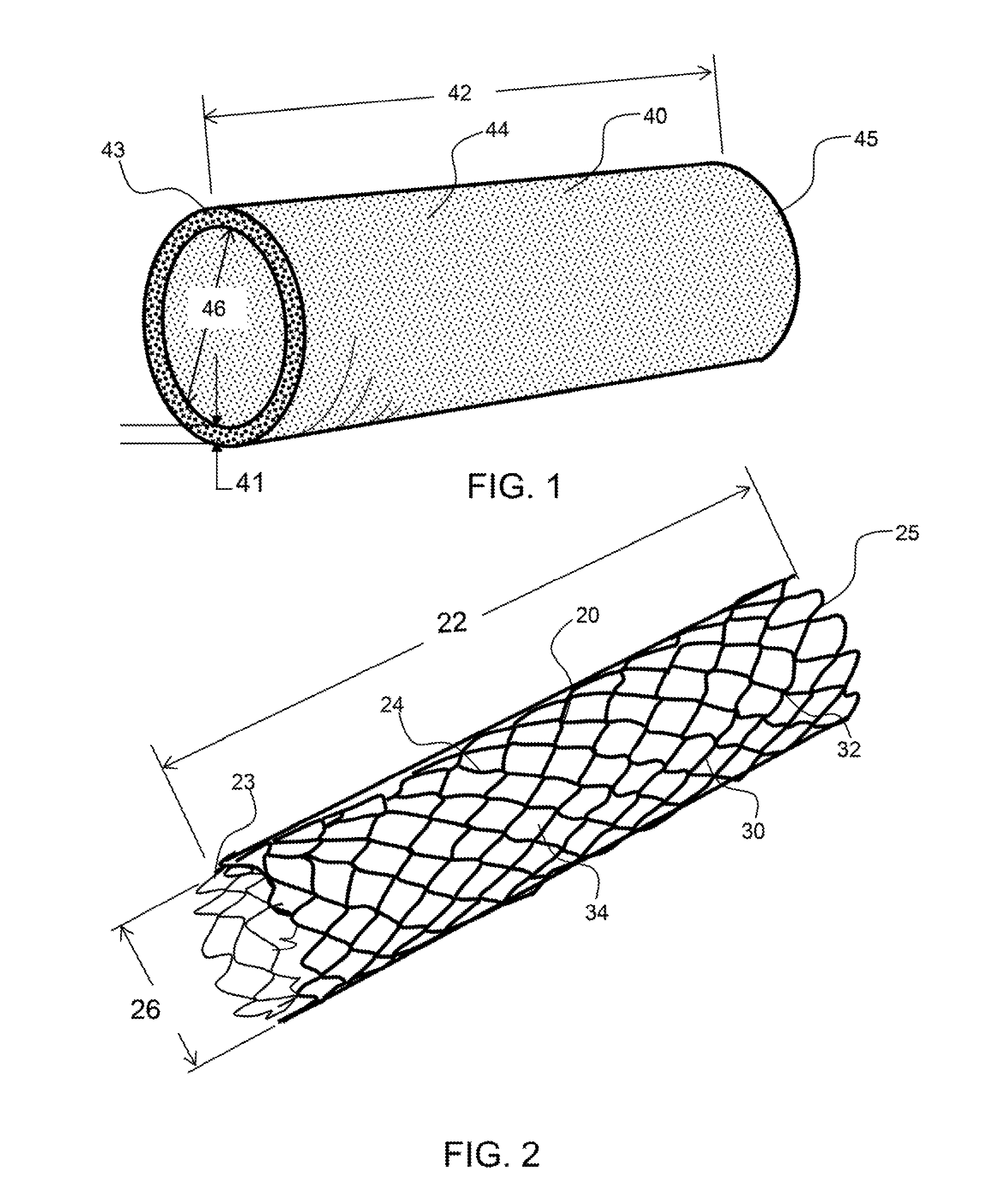
[0015]FIG. 1 shows a perspective view of an exemplary graft that is a cylindrical tube having a free graft diameter.

[0016]FIG. 2 shows a perspective view of an exemplary stent having a free stent diameter.

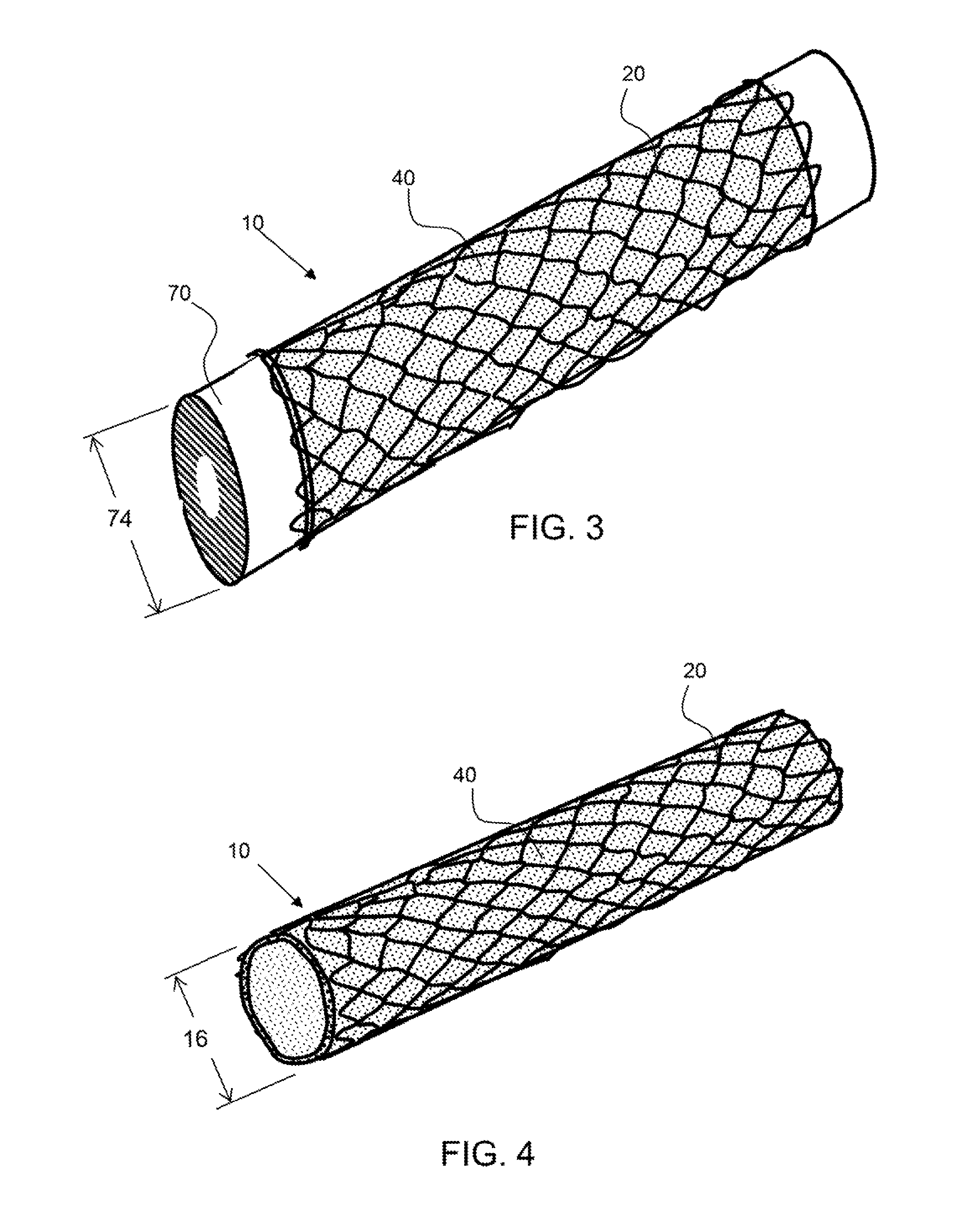
[0017]FIG. 3 shows a perspective view of an exemplary stent graft having the graft configured around a mandrel having a diameter that is substantially the same as the free graft diameter, and the stent configured around the outer surface of the graft, wherein the stent is radially expanded from a free stent diameter to the free graft diameter and configured over the graft.

[0018]FIG. 4 shows a perspective view of the exemplary stent graft of FIG. 3 removed from the mandrel wherein the stent has radially compressed the stent graft down in diameter to less than the free graft diameter.

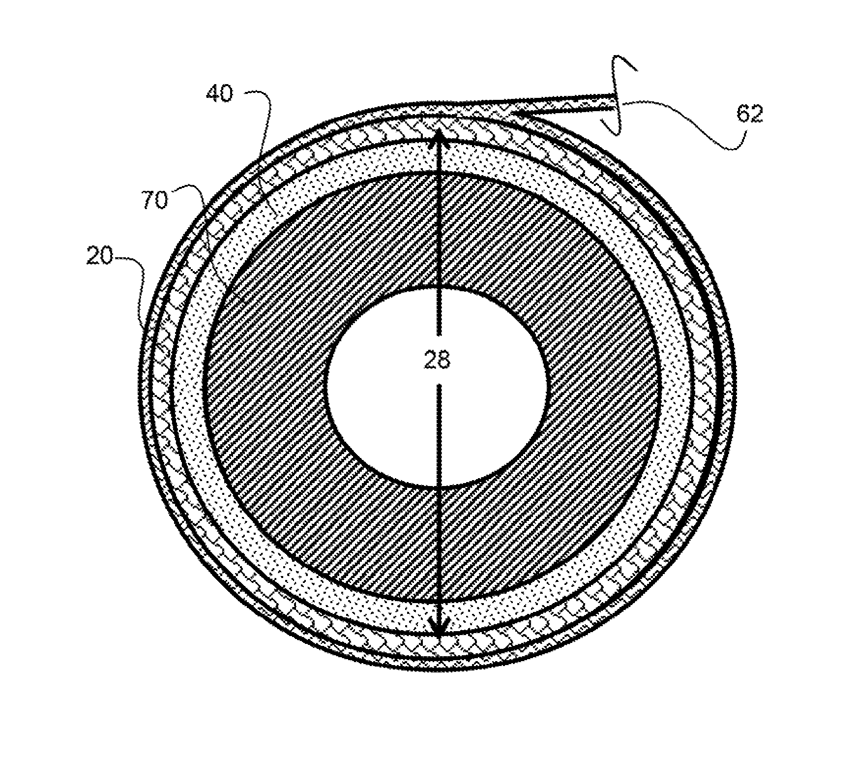
[0019]FIG. 5 shows a cross-sectional view of an exemplary graft configured over a mandrel having a diameter that is substantially the same as the free graft diameter.

[0020]FIG. 6 shows a cross-sectional ...


PUM


Abstract

A radially compliant pressure indicating stent graft is radially compliant from a free stent graft diameter to an expanded stent graft diameter. A radially compliant slant is attached to a graft having stored circumferential length between attachment points. A slant may be expanded and affixed to the graft or the graft may be constricted radially and the stent attached to the constricted graft. The radially compliant stent graft may expand radially to a free graft diameter and the graft may be non-elastic and / or no compliant. As the stent graft approaches the free graft diameter, the force to expand further may increase rapidly.

Description

BACKGROUND OF THE INVENTION[0001]Field of the Invention[0002]The present invention relates to radially compliant stent grafts that may be used to indicate a pressure differential across the wall of the radially compliant stent graft.[0003]Background[0004]Stents made out of super elastic materials, such as Nitinol, have been used to produce radially compliant stents. However, grafts made out of fluoropolymers, such as expanded PTFE, are not elastic. Stents and grafts are combined to produce self-expanding stent grafts that are radially compliant in compression only, as the graft is not elastic. The graft can be radially compressed but cannot be radially expanded as it will stretch and damage the graft material. Typically, a stent graft is constricted down in diameter and retained in this constricted state until positioned within the vasculature for deployment, where the stent graft is expanded radially within the vasculature. In most cases, the stent graft is oversized, wherein the s...

Claims


Application Information

Patent Timeline
IPC IPC(8): A61F2/07A61F2/90
CPCA61F2/07A61F2/90A61F2002/075A61F2240/002A61F2210/0014A61F2240/001A61F2250/0018
Inventor ZUKOWSKI, STANISLAW L
Owner ZUKOWSKI STANISLAW L
Learn More