
Electronic device for vehicle

a technology for electronic devices and vehicles, applied in electrical equipment, electrical apparatus, cooling/ventilation/heating modifications, etc., can solve the problems of electronic instruments becoming unusable, components being damaged, etc., and achieve the effect of reducing the lifespan reducing the deterioration and increasing the speed of the flash memory

Active Publication Date: 2017-03-07
DENSO CORP
View PDF23 Cites 4 Cited by
  • Summary
  • Abstract
  • Description
  • Claims
  • Application Information

AI Technical Summary

Benefits of technology

[0005]The ambient operating temperature of various kinds of component is raised in a vehicle (for example, an automobile), and the deteriorating speed of the flash memory increases more. If consideration is not given to the thermal environment of each individual component in the vehicle, the component will be damaged, and an electronic instrument will become unusable, before the lifespan of the vehicle expires. In case where a heat radiating device such as a CPU or a power supply management IC is mounted on the same substrate, and where a volatile memory is further mounted on the same substrate, if a flash memory is indiscriminately mounted on the substrate, the deteriorating speed of the flash memory becomes faster, and the lifespan of the flash memory is shortened.
[0006]An object of the disclosure is to provide an electronic device for a vehicle, in which a semiconductor package with a flash memory is disposed at an appropriate position on a multilayer digital substrate having a multiple of semiconductor packages respectively with a CPU, a volatile memory, a flash memory, and a power supply management IC, whereby the lifespan of the flash memory can be increased.
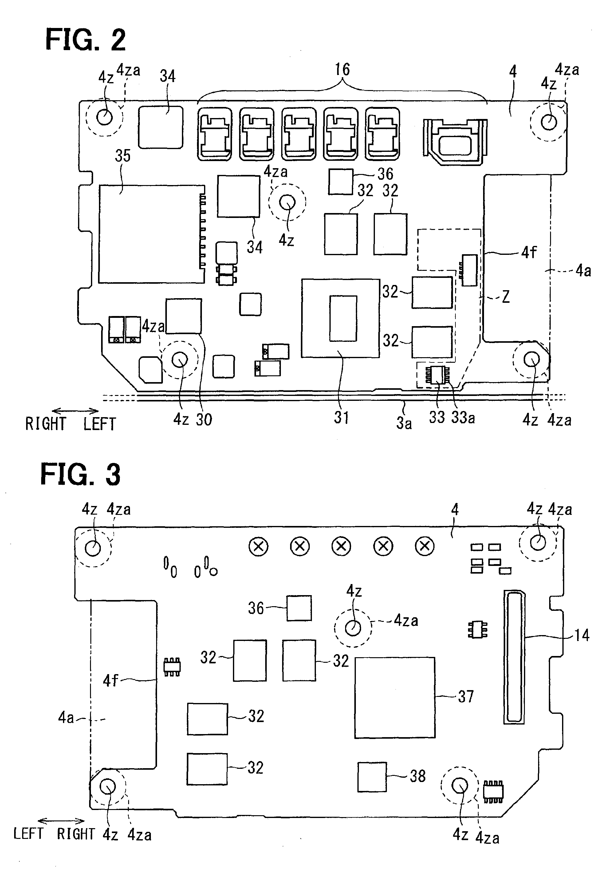
[0007]According to an aspect of the present disclosure, an electronic component is mounted to a multilayer digital substrate, and includes the first to fourth semiconductor packages respectively with a CPU, a volatile memory, a flash memory, and a power supply management IC. A fan takes in air along a surface of the digital substrate on which the first to fourth semiconductor packages are mounted. Because the third semiconductor package is disposed to distance from the first semiconductor package by at least a first predetermined distance and to distance from the fourth semiconductor package by at least a second predetermined distance, the effect of heat generated by the CPU and the power supply management IC can be minimized. Also, as the third semiconductor package is disposed in a passage of the air taken in by the fan, the third semiconductor package can be efficiently cooled.
[0009]A lead pin of the third semiconductor package is disposed to distance from a metal piece. Therefore, working is easy, for example when an operator electrically connects a probe to the lead pin and rewrites the data stored in the flash memory.

Problems solved by technology

If consideration is not given to the thermal environment of each individual component in the vehicle, the component will be damaged, and an electronic instrument will become unusable, before the lifespan of the vehicle expires.

Method used


Image

  • Electronic device for vehicle
  • Electronic device for vehicle
  • Electronic device for vehicle

Examples


Embodiment Construction

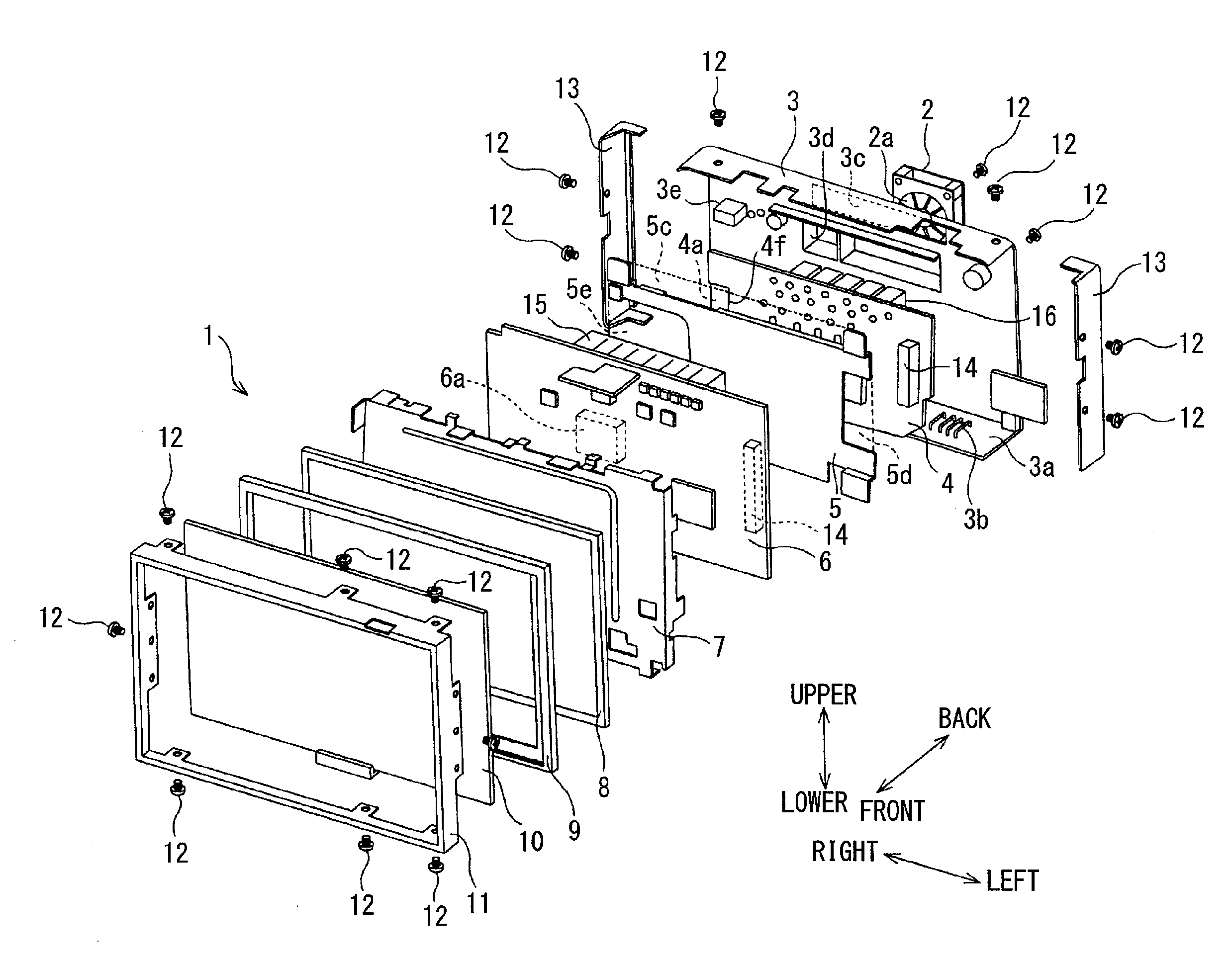
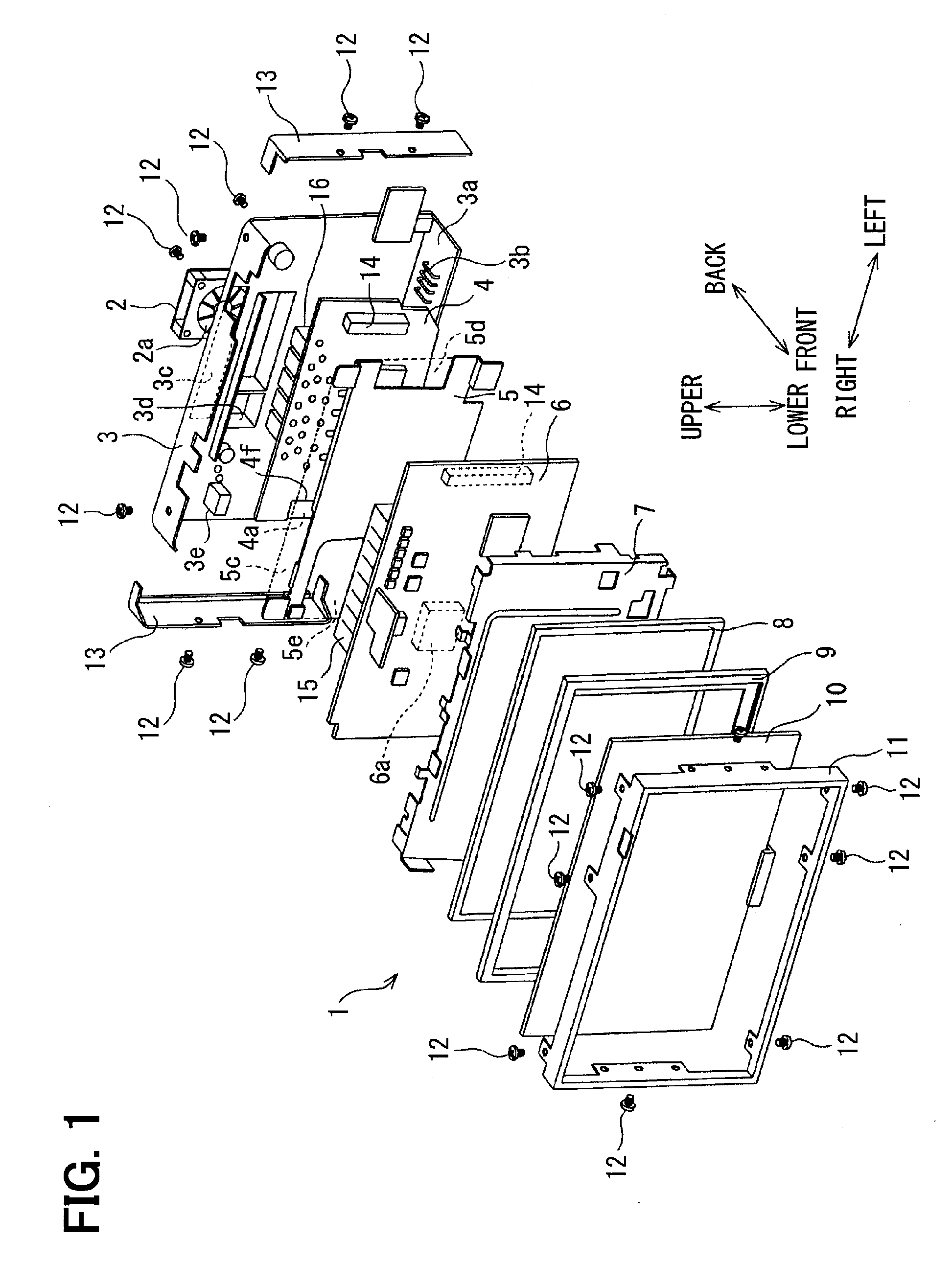
[0022]An embodiment of the disclosure will be described referring to FIG. 1 to FIG. 11. As shown in FIG. 1, an electronic device 1 for a vehicle has a back cover 3 made of metal at the backmost portion. A centrifugal fan unit 2 is mounted to the back cover 3. A printed circuit board (digital substrate) 4 to which a digital circuit is mounted, an inter-substrate frame 5, a printed circuit board (interface substrate) 6 to which an interface circuit is mounted, a top frame 7, a liquid crystal display (LCD) 8, an intermediate retaining frame 9, a touch panel 10, and an external frame 11 are assembled, in this order, using screws 12, positioned on the front side of the back cover 3. Side plates 13 are assembled on the lateral sides using screws 12.

[0023]Of these parts, the touch panel 10, the LCD 8, the top frame 7, the interface substrate 6, the inter-substrate frame 5, and the digital substrate 4 are parts having approximate plate form, which are stacked in the previously mentioned ord...


PUM


Abstract

An electronic device for a vehicle includes: a digital substrate having a first semiconductor package with a CPU, a second semiconductor package with a volatile memory readable and writable from the CPU, a third semiconductor package with a flash memory storing a start-up program of the CPU, and a fourth semiconductor package with a power supply management integrated circuit; and a fan that takes in air along the surface of the digital substrate on which the first to fourth semiconductor packages are mounted. The third semiconductor package is disposed to distance from the first semiconductor package by at least a first predetermined distance and to distance from the fourth semiconductor package by at least a second predetermined distance exceeding the first predetermined distance, and is disposed in a passage of the air taken in by the fan.

Description

CROSS REFERENCE TO RELATED APPLICATION[0001]This application is a U.S. national stage of International Application No. PCT / JP2013 / 006581 filed on Nov. 8, 2013 and is based on Japanese Patent Application No. 2013-41904 filed on Mar. 4, 2013, the disclosures of which are incorporated herein by reference.TECHNICAL FIELD[0002]The present disclosure relates to an electronic device for a vehicle.BACKGROUND ART[0003]An electronic device for a vehicle has, for example, a CPU, a volatile memory, and a flash memory, and carries out various kinds of processing relating to various kinds of vehicle. In recent years, a flash memory is used for storing a start-up program for starting up an electronic device for a vehicle. The flash memory is a rewritable memory, and in recent years, stored data can be rewritten after the flash memory is mounted on a substrate (for example, refer to Patent Literature 1).PRIOR ART LITERATURESPatent Literature[0004]Patent Literature 1: JP 2009-176147 ASUMMARY OF INVE...

Claims


Application Information

Patent Timeline
Patent Type & Authority Patents(United States)
IPC IPC(8): H05K7/20H05K5/00
CPCH05K7/20136H05K5/0004H05K7/20863H05K7/20972
Inventor SUEYOSHI, TETSUYAKAWASHITA, TSUBASAYOSHIDA, ICHIROSAWADA, KIYOHIKO
Owner DENSO CORP
Learn More