Method for operating a waste heat steam generator

a waste heat steam generator and waste heat technology, applied in steam engine plants, lighting and heating apparatus, boiler control, etc., can solve the problems of comparatively high risk of steam formation, and achieve the effect of avoiding excessive temperature fluctuations at the evaporator outlet and predicting and safe operation

Active Publication Date: 2017-03-14
SIEMENS ENERGY GLOBAL GMBH & CO KG
View PDF25 Cites 4 Cited by
  • Summary
  • Abstract
  • Description
  • Claims
  • Application Information

AI Technical Summary

Benefits of technology

[0014]The object underlying the invention is therefore to disclose a method for operating a waste heat steam generator of the aforementioned type as well as a waste heat steam generator which enable a higher level of operational safety and reliability in the control of the waste heat steam generator.
[0019]In an advantageous embodiment, the flow rate through the bypass line is reduced if the characteristic variable is increased. This enables the flow rate through the bypass line to be adjusted accordingly already when the thermal energy supplied to the waste heat steam generator is increased and therefore even before the measurement of an actual change in the temperature or, as the case may be, supercooling at the inlet of the evaporator. If, namely, the thermal flow volume supplied to the waste heat steam generator is increased in the current mode of operation of the waste heat steam generator, this is linked to an increase in magnitude of further thermodynamic (state) variables of the flow medium (such as feedwater mass flow, pressure, medium temperatures, for example), which is directly associated with an increase in the inlet supercooling due to physical principles. In this case, therefore, the flow rate through the bypass line is reduced, thereby causing the temperature at the outlet of the economizer to increase and thus reducing the supercooling at the evaporator inlet.
[0021]Predictively controlling or regulating the flow rate through the bypass line of the economizer in this way, such that the flow rate is adjusted already before a change in the temperature at the inlet of the evaporator is actually measured, is predicated on a real, reliable characteristic variable for the thermal energy supplied to the waste heat steam generator. In an advantageous embodiment, the power output of a gas turbine connected upstream of the waste heat steam generator on the flue gas side is used as the characteristic variable for the thermal energy supplied to the waste heat steam generator. In gas and steam turbine power plants, the flue gas is namely generated by such a gas turbine disposed upstream of the waste heat steam generator and the temperature or, as the case may be, volume of said flue gas varies with the instantaneous power output of the gas turbine. The power output of the upstream gas turbine is therefore characteristic of the thermal flow volume supplied to the waste heat steam generator and can furthermore be forwarded as an easy-to-read signal to a corresponding control device. Accordingly, a particularly simple control or regulation of the flow rate through the economizer bypass line is possible.
[0022]In waste heat steam generators it is frequently the case that not all heating surfaces of the economizer are provided with a bypass line, but instead the bypass line runs for example parallel to a number of economizer heating surfaces and the mixing point of bypass line and flow through said economizer heating surfaces is followed by one or more further economizer heating surfaces. The previously used temperature signal for regulating the flow rate through the bypass line is measured at the outlet of the last economizer heating surface and hence at the inlet of the evaporator. Accordingly, said signal, which measures the temperature difference caused by changes in the flow rate through the bypass line, is delayed firstly by the time that the flow medium needs to flow through the last economizer heating surfaces that are not provided with a bypass line, and secondly also by processes for storing thermal energy in the tube walls of said heating surfaces, the thermal capacity of which is likewise to be taken into account. A further improvement in the control or regulation speed could therefore be achieved if the temperature at the mixing point at the outlet of the bypass line is advantageously used for controlling or regulating the flow rate through the bypass line. It is therefore possible to provide an even more reliable and faster control or regulation and prevention of steam formation at the inlet of the evaporator.
[0025]For this reason in an advantageous embodiment the balanced flue gas heat of the evaporator should be used as a characteristic variable for the thermal energy supplied to the waste heat steam generator. The balanced flue gas heat is essentially determined from the mass flow of the flue gas on the one hand and the temperature difference at the inlet on the flue gas side and at the outlet of the evaporator on the other. In this case the inlet temperature is measured and the outlet temperature approximated by means of the saturation temperature of the evaporator. In practice this allows a direct measurement of the heat flow introduced into the evaporator—and consequently into the waste heat steam generator. Furthermore, this signal is often already present in control devices for waste heat steam generators, since it can be used for feedwater regulation. Through the use of this signal the quality of control or regulation can be further improved and adequate supercooling at the inlet of the evaporator assured with even greater reliability.
[0028]The advantages associated with the invention consist in particular in that through the use of a variable that is characteristic of the thermal energy supplied to the waste heat steam generator for controlling or regulating the flow rate through the bypass line of the economizer of a waste heat steam generator, predictable and safe operation can be assured by means of the reliable setting of the supercooling at the evaporator inlet. Furthermore, excessive temperature fluctuations at the evaporator outlet are avoided, which is accompanied by further advantages for example with regard to the thick-walled components of the water-steam separator connected downstream of the evaporator. The method is therefore suitable in particular for modern gas and steam turbine power plants in which rapid load changes are frequently necessary.

Problems solved by technology

In this case the risk of steam formation is comparatively great in particular in the event of rapid changes in load, since here a comparatively rapid change in the supercooling at the inlet of the evaporator is present.

Method used


Image

  • Method for operating a waste heat steam generator
  • Method for operating a waste heat steam generator
  • Method for operating a waste heat steam generator

Examples


Embodiment Construction

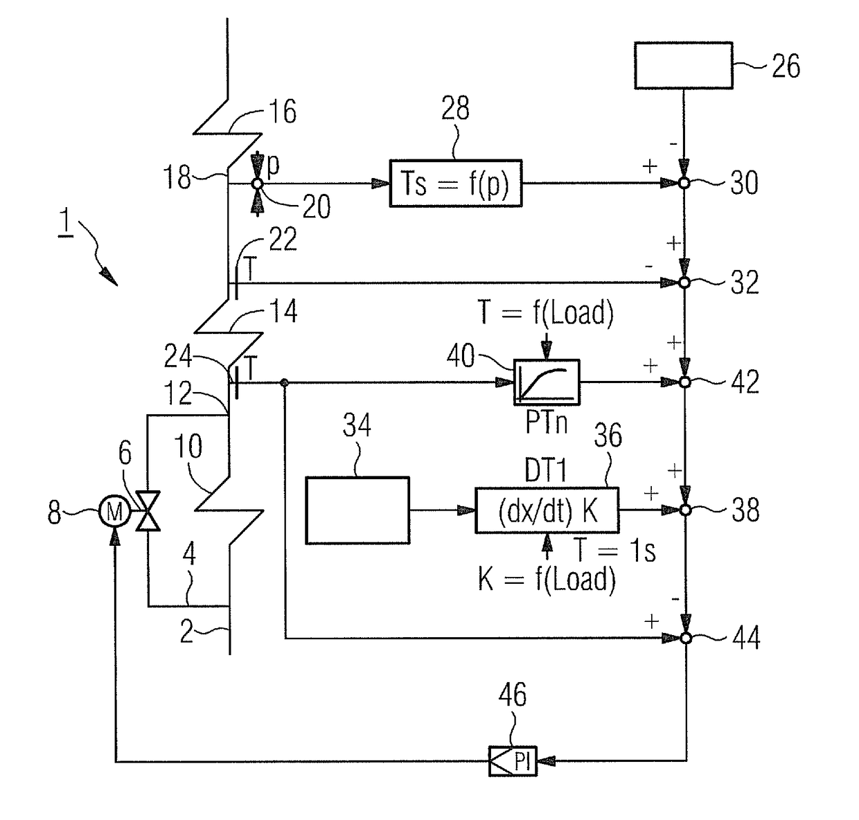
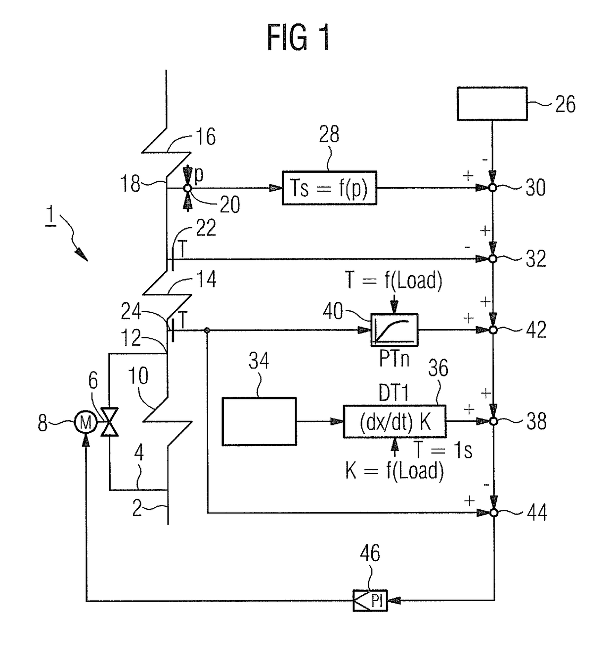
[0033]FIG. 1 firstly shows in schematic form selected components of a waste heat steam generator 1. Flow medium, driven by means of a pump (not shown), flows into the circuit initially at the inlet 2, a bypass line 4 initially branching off. In order to regulate the flow through the bypass line, a flow regulator valve 6 is provided which is controllable by means of a motor 8. A simple control valve may also be provided, although a better adjustment of the supercooling at the evaporator inlet is possible by means of a rapidly responding regulator valve.

[0034]A part of the flow medium consequently flows into the bypass line 4 as a function of the position of the flow regulator valve 6, while another part flows into a first economizer heating surface 10. Further economizer heating surfaces can also be provided in parallel with the bypass line 4. At the outlet of the economizer heating surface 10 the flow medium from the bypass line 4 and the flow medium from the economizer heating surf...


PUM


Abstract

A method for operating a waste heat steam generator including an evaporator, an economizer having a number of economizer heating surfaces, and a bypass line connected on the flow medium side in parallel with a number of economizer heating surfaces is provided. The method makes possible higher operational safety and reliability in the control of the waste heat steam generator. For this purpose, a parameter that is characteristic of the thermal energy fed to the waste heat steam generator is used to control or regulate the flow rate of the by-pass line.

Description

CROSS REFERENCE TO RELATED APPLICATIONS[0001]This application is the U.S. National Stage of International Application No. PCT / EP2009 / 064263, filed Oct. 29, 2009 and claims the benefit thereof. The International Application claims the benefits of European Patent Office application No. 08019862.5 EP filed Nov. 13, 2008. All of the applications are incorporated by reference herein in their entirety.FIELD OF INVENTION[0002]The invention relates to a method for operating a waste heat steam generator having an evaporator, having an economizer with a number of economizer heating surfaces, and having a bypass line connected in parallel with a number of economizer heating surfaces on the flow medium side.BACKGROUND OF INVENTION[0003]A waste heat steam generator is a heat exchanger which recovers heat from a hot gas flow. Waste heat steam generators are deployed for example in gas and steam turbine power stations in which the hot exhaust gases of one or more gas turbines are conducted into a ...

Claims


Application Information

Patent Timeline
Patent Type & Authority Patents(United States)
IPC IPC(8): F01K13/00F01K13/02F22B35/00F01K23/10
CPCF22B35/007F01K13/02F01K23/101Y02E20/16F22B35/00F01K23/10
Inventor BRUCKNER, JANTHOMAS, FRANK
Owner SIEMENS ENERGY GLOBAL GMBH & CO KG
Why Eureka
Try Eureka