Triple helix driveline cable and methods of assembly and use

a driveline cable and triple helix technology, applied in the direction of cables, insulated conductors, conductors, etc., can solve the problems of heart failure, increased stress, and increased risk of heart failure, so as to reduce stress, improve durability, and increase strength

Active Publication Date: 2017-03-28
TC1 LLC
View PDF54 Cites 22 Cited by
  • Summary
  • Abstract
  • Description
  • Claims
  • Application Information

AI Technical Summary

Benefits of technology

[0008]In one aspect, the cable includes conductors formed of multiple uninsulated wire strands that are loosely packed and assembled in a triple-helix configuration formed by three sequential winding operations in which the wire strands are wound along three distinct axes. For example, the wire strands may be wound in a first winding pattern to form multiple uninsulated bunches that are wound in a second winding pattern to form bundles of bunches, after which multiple bundles are wound in a third winding pattern to form the conductor. The multiple insulated conductors are then wound in a fourth pattern to form the cable. The conductors may be wound around a central core, such as a polymer member, to provide additional strength to the cable. The fourth winding pattern may including winding the conductors at 0.75 inch pitch or less along the longitudinal axis of the cable, such as a 0.6 inch pitch, so as to provide a spring-like effect that further reduces stresses and improves durability of the cable.

Problems solved by technology

People with heart failure often have shortness of breath and fatigue.
Years of living with blocked arteries or high blood pressure can leave your heart too weak to pump enough blood to your body.
As symptoms worsen, advanced heart failure develops.
Since loss of power of an implanted VAD or failure to recharge an associated power supply poses life threatening consequences, to ensure continuous operation of the VAD, the driveline cable must provide a dependable electrical connection.

Method used


Image

  • Triple helix driveline cable and methods of assembly and use
  • Triple helix driveline cable and methods of assembly and use
  • Triple helix driveline cable and methods of assembly and use

Examples


Embodiment Construction

[0020]The invention relates generally to power cables, and in one embodiment, to a driveline cable for powering a mechanical circulatory support system, such as VAD. Various aspects of the invention are similar to those described in U.S. Pat. No. 8,562,508 entitled “Mobility-Enhancing Blood Pump System,” filed Dec. 30, 2009; U.S. Application Publication No. 2012 / 0149229 entitled “Modular Driveline,” published on Jun. 14, 2012; and U.S. Pat. No. 8,682,431 entitled “Driveline Cable Assembly,” filed Jan. 23, 2013; each of which the entire contents are incorporated herein by reference for all purposes.

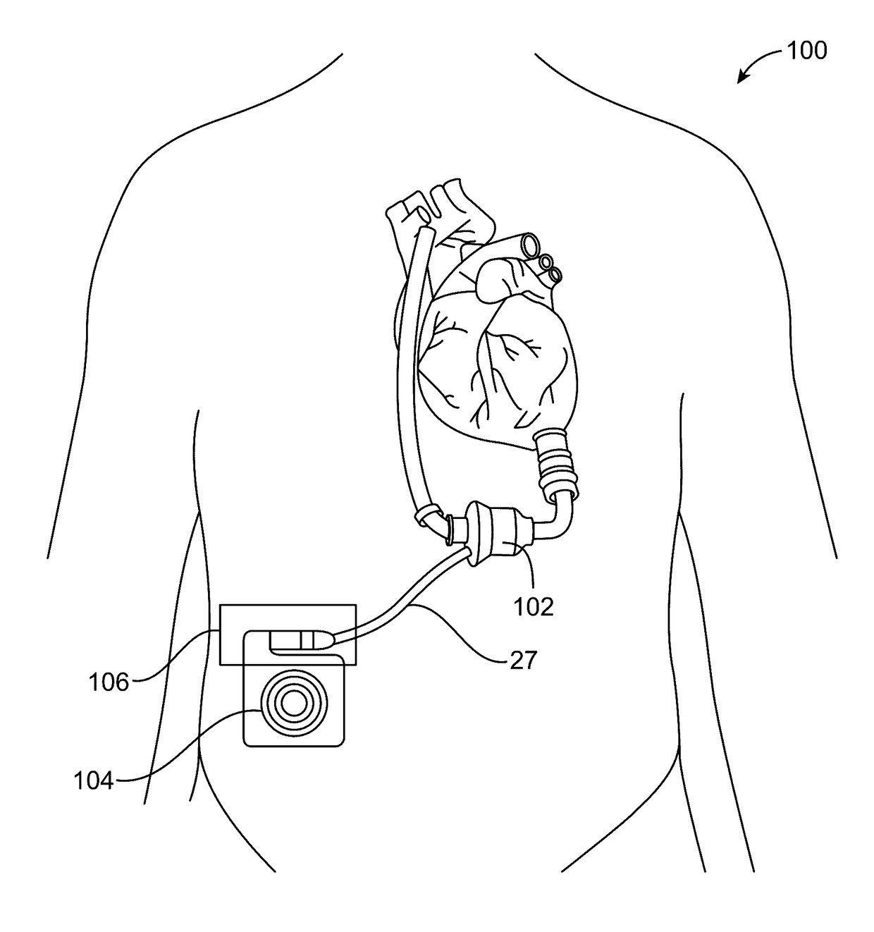
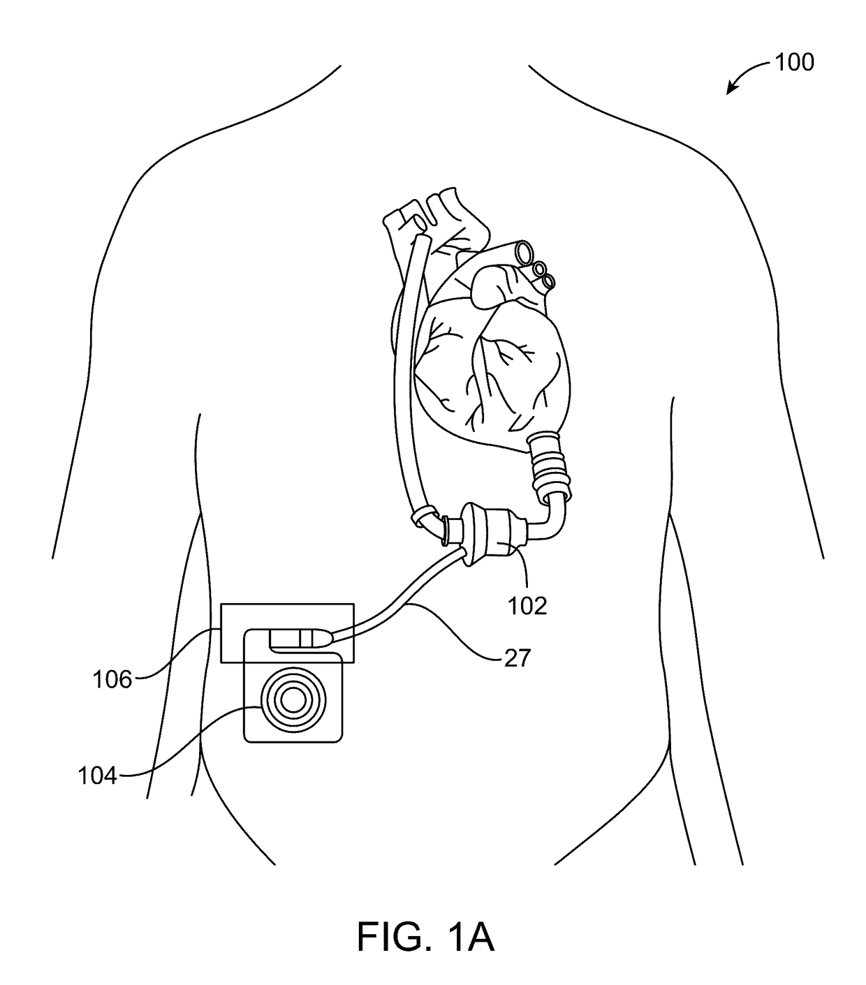
[0021]FIG. 1A illustrates an medical system 100 that includes an implantable medical device 102, shown as a VAD, and an implanted module 104 configured to receive wireless power from outside the body to provide power for the medical device. A bulkhead connector 106 and drive line cable 27 connect the implanted module to the medical device to provide power, data, and or / control signals from...


PUM

PropertyMeasurementUnit
frequencyaaaaaaaaaa
voltagesaaaaaaaaaa
voltagesaaaaaaaaaa

Abstract

A power cable having improved durability and associated methods of assembly and use are described herein. In one aspect, the power cable is adapted for use in powering an implantable circulatory pump system. The cable includes one or more conductors of uninsulated wire strands that are loosely packed so as to move relative one another during cable flexure. The driveline cable may include a plurality of conductors, each comprised of multiple uninsulated bundles of uninsulated, loosely packed wire strands of a conductive material, that are wrapped about a central core. The cable may include at least six conductors, each conductor having at least 200 wire strands of a 30 gauge or higher. The cable may include the plurality of wire strands wound in a Litz style configuration to provide improved durability over many cycles of use at reduced cost, improved integrity of the electrical connection and reduced diameter.

Description

REFERENCES TO RELATED APPLICATIONS[0001]This application is a Non-Provisional of and claims the benefit of priority of U.S. Provisional Application No. 62 / 045,365 filed on Sep. 3, 2014, the entire contents of which are incorporated herein by reference.BACKGROUND OF THE INVENTION[0002]This application relates generally to power cables, and particularly to power cables for low frequency AC and DC applications, such as may be used for a driveline cable to power implantable mechanical circulatory support systems.[0003]Ventricular assist devices, known as VADs, are implantable blood pumps used for both short-term (i.e., hours, days, months) and long-term applications (i.e., years or a lifetime) where a patient's heart is incapable of providing adequate circulation, for example, due to heart failure. According to the American Heart Association, more than five million Americans are living with heart failure, with about 670,000 new cases diagnosed every year. People with heart failure often...

Claims


Application Information

Patent Timeline
Patent Type & Authority Patents(United States)
IPC IPC(8): A61N1/362H01B1/02H01B7/04A61M1/12
CPCA61M1/127H01B1/026H01B7/048A61M1/122A61M2205/04A61M60/148A61M60/82A61M60/824A61M60/88A61M60/232A61M60/422A61M60/237A61M60/178A61M60/825
Inventor ROMERO, JAIMEHAROLD, NATHAN
Owner TC1 LLC
Why Eureka
Try Eureka