Method and apparatus for shortening the rotor blades of a turbomachine

a turbomachine and rotor blade technology, which is applied in the field of shortening the rotor blade of a turbomachine, can solve the problems of long machining time associated with automatic feed, complex grinding apparatus and high cost, and the blades of turbomachines are subjected to very high material loading and corresponding high wear, so as to achieve the effect of reducing the cost of machining and quick

Active Publication Date: 2017-04-11
SIEMENS ENERGY GLOBAL GMBH & CO KG
View PDF17 Cites 3 Cited by
  • Summary
  • Abstract
  • Description
  • Claims
  • Application Information

AI Technical Summary

Benefits of technology

[0012]Proceeding from this prior art, it is an object of the present invention to provide a method for shortening a rotor blade of a turbomachine of the type mentioned in the introduction and apparatus for carrying out such a method, by means of which rotor blades can be shortened cost-effectively and quickly. Preferably the grinding step gives the blade tip a conical contour and relative movement of the belt grinding apparatus and the blade tips are adjusted during grinding to shape the blade tip.
[0013]The present invention achieves this object by providing a method for shortening the rotor blades of a turbomachine by removal of material at the blade tip, in which according to the invention a belt grinding apparatus is used to shorten the rotor blade. An essential advantage of using a belt grinding apparatus is that, by using a grinding belt which is wider than the blade tip to be shortened, the entire blade tip can be machined in one pass. Accordingly, in contrast to grinding machining with a grinding disk and in contrast to milling machining, it is not necessary to move the grinding belt along the contour of the blade tip, which results in a compact, lightweight and cost-effective construction. In addition, the machining time is reduced. According to the first estimates of the applicant, it is possible to achieve a time saving of approximately 60% with respect to grinding with a straight grinding disk and even of 80 to 90% with respect to milling machining. The higher costs for the grinding belts with respect to a straight grinding disk are compensated for by markedly shorter machining times. This is also the case for the shorter downtimes of grinding belts in comparison with grinding disks and milling cutters. A further advantage of using a belt grinding apparatus is that grinding belts are not as susceptible to transport damage as straight grinding disks and milling cutters. Furthermore, tests have shown that, when using a belt grinding apparatus, there is no risk of the ceramic coating of the blades breaking off. In addition, grinding machining with a grinding belt generates no or almost no burrs, which has the advantage that no or only limited manual post-treatments need be carried out. Yet a further advantage is that with the reduced machining time also comes a reduced hazard period for staff.
[0014]According to a first configuration of the method according to the invention, the rotor blades remain installed in a casing of the turbomachine during the shortening, wherein the method has the steps of: removing a casing part, at least partially exposing the rotor blades to be machined and exposing a parting joint of the casing; attaching a belt grinding apparatus to the parting joint of the casing in the region of the rotor blades to be machined; orienting the belt grinding apparatus relative to the rotor blades to be shortened and shortening the rotor blades in situ using the belt grinding apparatus while the rotor is continuously rotated and the grinding dust produced during the grinding machining is extracted. This method variant is in particular characterized in that the rotor blades need not be removed, implying little effort, a significant time saving and low costs. Furthermore, by machining the blades in the installed state, all the tolerance chains for producing an intended blade gap are automatically taken into account, which leads to an optimum machining result.
[0020]Preferably, grinding dust produced during the grinding machining is extracted in order to avoid pollution of the surroundings and to protect the operator from potentially toxic or at least harmful dust.
[0022]The present invention achieves the object stated in the introduction by further providing a belt grinding apparatus for carrying out the first method variant according to the invention, comprising a motor, at least one grinding belt driven by the motor, a feed / travel device which is configured so as to carry out the feed and travel movement of the grinding belt, an orienting device which is configured so as to orient relative to each other the grinding belt and the rotor blades to be shortened, an extraction device and an attachment device which is configured so as to attach a belt grinding apparatus to a parting joint of a casing of a turbomachine. A belt grinding apparatus of this type is noteworthy in particular in that it can be attached directly to the casing of a turbomachine and can machine rotor blades in situ.
[0025]The extraction device should contain a suitable filter in order to minimize contamination with carcinogenic grinding dust and to reliably prevent dust explosions. It should also be strong enough to keep the cooling bores of the blades free from dust. In addition, the grinding belt can also be largely provided with a shroud which suitably supports the extraction device. Brushes or baffles, which keep the dust in the desired machining region, may be used to protect the blades.

Problems solved by technology

During operation, blades of turbomachines, in particular turbine blades, are subjected to very high material loading and to corresponding high wear.
One disadvantage of the grinding apparatuses with a straight grinding disk, used to shorten rotor blades, is that on account of the limited width of the grinding disk, which is approximately 20 mm in mobile use, it is necessary to move the grinding disk along the contour of the blade tip.
Accordingly, an automatic feed is necessary, which leads to a complex construction of the grinding apparatus and to high costs.
Furthermore, a long machining time is associated with the automatic feed.
One disadvantage of the milling methods used to shorten rotor blades of a turbomachine is, on one hand, that these are very expensive, which is not least due to the high initial costs of the CNC milling machines used and the high tool costs.
On the other hand, the milling methods are very slow.

Method used


Image

  • Method and apparatus for shortening the rotor blades of a turbomachine
  • Method and apparatus for shortening the rotor blades of a turbomachine
  • Method and apparatus for shortening the rotor blades of a turbomachine

Examples


Embodiment Construction

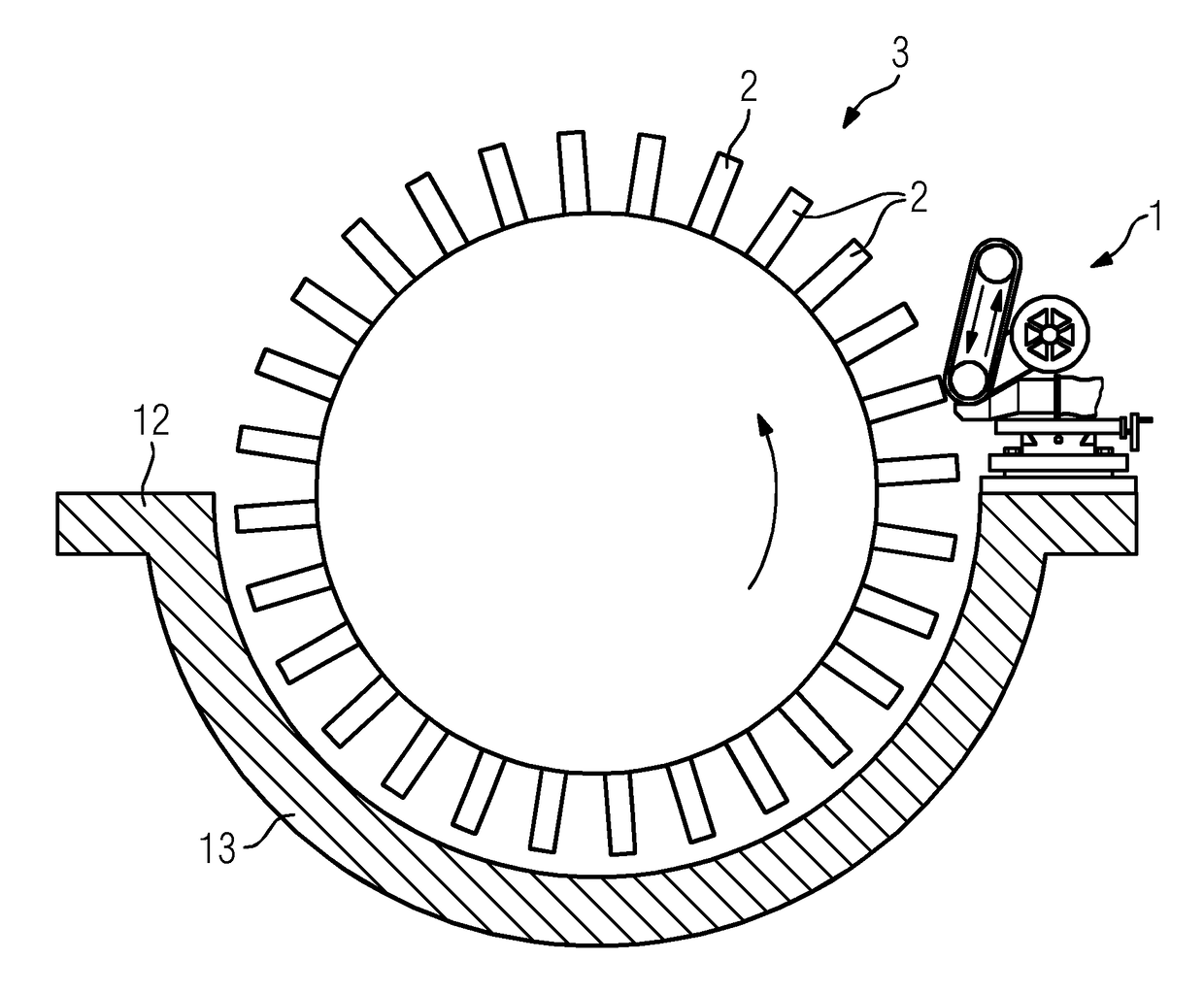
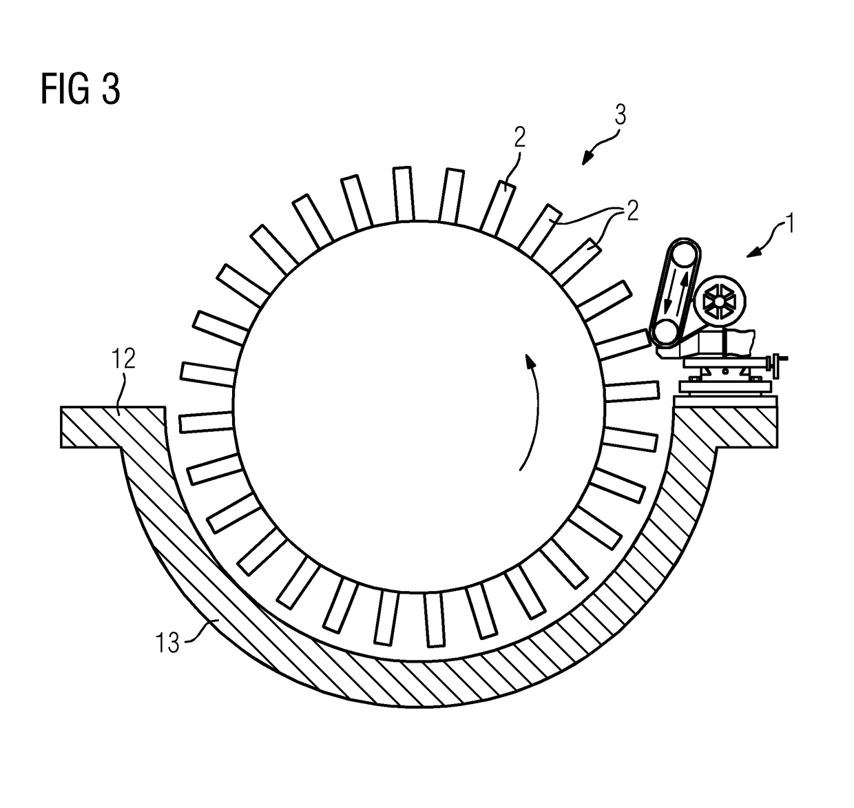
[0036]The belt grinding apparatus 1 comprises a motor 4, a grinding belt 5 which is driven by the motor 4 and is laid around a contact roller 6 and a tensioning roller 7 and is tensioned between these, a feed / travel device 8 and an orienting device 9, wherein the abovementioned components are arranged on a base plate 10. The belt grinding apparatus 1 further comprises an attachment device 11 by means of which the base plate 10 can be attached to a parting joint 12 of a lower casing half 13 of the turbomachine 3.

[0037]The feed / travel device 8 is configured so as to carry out the feed and travel movement of the grinding belt 5 and in the present case is formed by a cross table. With the aid of the feed / travel device 8, the grinding belt 5 may be moved in mutually perpendicular directions by actuating corresponding handwheels 14 and 15, as indicated by the double arrows 16 and 17.

[0038]In the present case, the orienting device 9 is formed by a rotatably mounted plate which is rotated b...


PUM


Abstract

A method for shortening one or more rotor blade(s) (2) of a turbomachine (3) by removal of material at the blade tip, and apparatus (1; 19) for carrying out the method: a belt grinding apparatus (1; 19) shortens the rotor blades (2) and a contour of the blade tip is generated by a relative movement of the blade tip along the static belt grinding apparatus.

Description

CROSS-REFERENCE TO RELATED APPLICATIONS[0001]The present application claims priority of European Patent Application No. EP 13189998, filed Oct. 24, 2013, the contents of which are incorporated by reference herein.TECHNICAL FIELD[0002]The present invention relates to a method for shortening the rotor blades of a turbomachine by removal of material at the blade tip, and to apparatuses for carrying out such a method.TECHNICAL BACKGROUND[0003]During operation, blades of turbomachines, in particular turbine blades, are subjected to very high material loading and to corresponding high wear. For this reason, the blades are replaced with new blades within the framework of maintenance work, normally after a predetermined operating time. In that context, the operating time is advantageously chosen such that the replaced blades may still be repaired.[0004]If the blades of a turbine are replaced, the turbine rotor blades, the turbine stator vanes and the guiding segments are replaced. In order ...

Claims


Application Information

Patent Timeline
Patent Type & Authority Patents(United States)
IPC IPC(8): B24B21/16B24B19/14B24B21/00B24B55/10B23Q11/00B24B55/08
CPCB24B21/165B23Q11/0046B24B55/08B24B55/10Y02P70/171B24B55/107F01D5/12Y02P70/10F01D5/18F05D2230/10F05D2240/307
Inventor GENZ, ALEXANDERLIEDTKE, SAMUELLOHSE, FLORIAN
Owner SIEMENS ENERGY GLOBAL GMBH & CO KG
Why Eureka
Try Eureka