Decoupling of split ring resonators in magnetic resonance tomography

a technology of magnetic resonance tomography and split ring resonators, which is applied in the direction of magnetic resonance measurement, measurement devices, instruments, etc., can solve the problems of large restriction of the efficiency of the magnetic resonance tomograph, lengthening the read and/or scan time, and being more complex. , to achieve the effect of high quality

Active Publication Date: 2017-04-11
SIEMENS HEALTHCARE GMBH
View PDF25 Cites 1 Cited by
  • Summary
  • Abstract
  • Description
  • Claims
  • Application Information

AI Technical Summary

Benefits of technology

[0013]In a further embodiment, the interlocking ring structures have a polygonal shape. The polygonal shape greatly simplifies optimization of the decoupling, since the individual gaps of the metal conductor elements need no longer be displaced.
[0014]In a further embodiment, at least two split ring resonators may be matched / decoupled as a function of a configuration of the polygonal shape of the interlocking ring structures and / or overlap regions. Matching and / or decoupling without any change in the region of the gaps may be provided with a polygonal shape (e.g., a hexagonal structure). Decoupling may easily be set by varying the polygonal shape of the interlocking metal conductor elements of the ring structures and / or surface of the overlap regions.
[0017]A further aspect relates to a magnetic resonance tomography device with an arrangement of a plurality of split ring resonators. A magnetic resonance tomography device provided with an arrangement of a plurality of split ring resonators permits high quality images to be taken and provided, since the signal-to-noise ratio of the device is low owing to the decoupling of the plurality of split ring resonators.

Problems solved by technology

Increasing the magnetic field strength, however, is automatically accompanied by an increase in the design space for the magnetic resonance tomographs with control, in addition, that is also more complex.
A further possibility, specifically the lengthening of the read and / or scan time, may not be justified since the service life and / or efficiency of a magnetic resonance tomograph is greatly restricted.
However, this solution may not be employed in the case of relatively large objects and / or fields of view.
However, increasing the number of antennas gives rise, owing to the inductive coupling and thus influence from the individual antennas, to harmful side effects that restrict an increase in performance regarding the quality of information and / or images.
The attempts to date to decouple the individual antennas have been very complicated and expensive.
Decoupling the SRRs has been complicated and costly.
HF substrates are, however, complicated to produce, and therefore very expensive.
Disregarding the production costs, this solution further uses complicated matching.

Method used


Image

  • Decoupling of split ring resonators in magnetic resonance tomography
  • Decoupling of split ring resonators in magnetic resonance tomography
  • Decoupling of split ring resonators in magnetic resonance tomography

Examples


Embodiment Construction

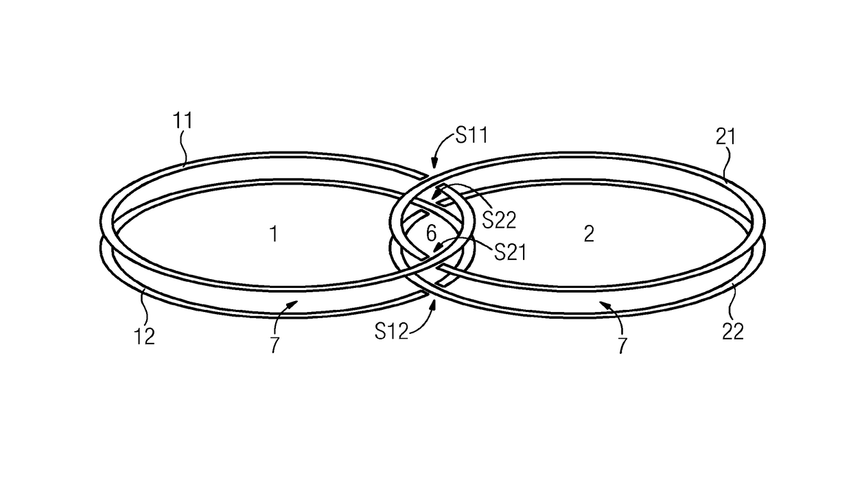
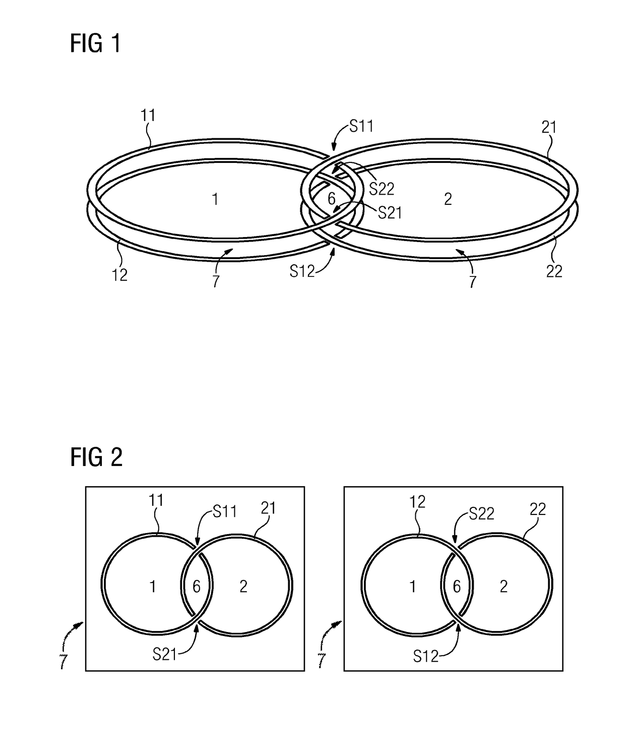
[0022]A perspective view of an embodiment of an arrangement with two split ring resonators 1, 2 is illustrated in FIG. 1 in a simplified fashion. A split ring resonator 1, 2 respectively includes two mutually parallel ring structures 11, 12; 21, 22 of a metal conductor element spaced apart by a substrate 7. The two mutually parallel ring structures 11, 12; 21, 22 are respectively separated by at least one gap S11, S21, S . . . ; S12, S22, S . . . . The two split ring resonators 1, 2 are arranged relative to one another such that the separated ring structures 11, 12 of the two split ring resonators 1, 2 may be reciprocally guided through a gap S11, S12 of the respective other ring structure 21, 22 with the associated gap S21, S22, and interlock. Overlap regions 6 are formed as interface of the respective ring structures 11, 21 and 12, 22. In anticipation of FIG. 2, which illustrates an upper and lower projection view into a substrate plane 7 in accordance with the embodiment from FIG...


PUM


Abstract

An arrangement includes a plurality of split ring resonators on a planar substrate. Each split ring resonator of the plurality of split ring resonators includes two mutually parallel ring structures of a metal conductor element spaced apart by the substrate. The two mutually parallel rings structures are respectively separated by at least one gap. At least two split ring resonators of the plurality of split ring resonators are positionable relative to one another such that the separated ring structures may be reciprocally guided through a gap of the respective other ring structures and interlock. Overlap regions may be produced by common ring structure inner surfaces.

Description

[0001]This application claims the benefit of DE 10 2012 217 760.4, filed on Sep. 28, 2012, which is hereby incorporated by reference.BACKGROUND[0002]The present embodiments relate to an arrangement of a plurality of split ring resonators on a planar substrate.[0003]Magnetic resonance tomography (MRT) has already been in use in radiology for a length of time. Magnetic resonance tomography is based on very strong magnetic fields and alternating magnetic fields in the radio frequency range that are used to excite specific atomic nuclei (e.g., mostly hydrogen nuclei / protons) in the body to move by resonance. The movement induces an electric signal in a receiver circuit. Specific MRT methods have been developed to be able to display information relating to the microstructure and function of the organs in addition to displaying position and shape.[0004]In order to provide a high quality of the images made with the aid of magnetic resonance tomography, antenna arrays that have a low signal...

Claims


Application Information

Patent Timeline
Patent Type & Authority Patents(United States)
IPC IPC(8): G01R33/34H01P1/203G01R33/3415G01R33/36H01P5/02
CPCH01P1/20381G01R33/34G01R33/3415G01R33/365H01P5/028
Inventor FACKELMEIER, ANDREASMARTIUS, SEBASTIAN
Owner SIEMENS HEALTHCARE GMBH
Why Eureka
Try Eureka