Cassette for pumping a treatment solution through a dialyzer

a dialyzer and dialyzer technology, applied in the field of dialyzers for pumping treatment solutions, can solve the problems of labor-intensive manufacture of such a supply arrangement, fluid leakage and/or operational failure, maintenance, etc., and achieve the effect of simple, accurate and robust metering of concentrates, reducing pneumatic pressure in the pump cavity, and high concentrate dosing accuracy

Active Publication Date: 2017-04-18
GAMBRO LUNDIA AB
View PDF21 Cites 0 Cited by
  • Summary
  • Abstract
  • Description
  • Claims
  • Application Information

AI Technical Summary

Benefits of technology

[0012]Another objective is to achieve an improved reliability of a supply arrangement for treatment solution in a dialysis system, for example with respect to operational failure and leakage.
[0060]It may be important to remove gases from the treatment solution, to ensure proper operation of the solution pumps and the dialyzer. One significant advantage of the inventive use of solution pumps with a gas-liquid interface is that gases, e.g. air, that may be entrapped or dissolved in the liquid that enters the pump cavity will at least partly be removed from the liquid during the filling phase when the pump cavity is communicated with the pneumatic manifold to lower the pneumatic pressure in the pump cavity. Thereby, the solution pump has an inherent gas removal function. In one embodiment, which may achieve a more consistent and efficient gas removal, the valve arrangement is operable, in a gas removal phase during operation of the cassette, to seal off the pump cavity from the hydraulic manifold and selectively communicate the pump cavity with the pneumatic manifold to establish a negative pressure in the pump cavity.

Problems solved by technology

The manufacturing of such a supply arrangement is labor intensive.
Also large number of connections and detachable and movable parts may lead to leakage of fluid and / or operational failure and need for maintenance.
Thus, manufacture is complex and the supply arrangement has many points of failure as well as many connections that may cause leakage.
It is realized that a failure in a moving component inside one of the cassettes results in rejection of the entire cassette, or even the entire cassette system, since it may be difficult or impossible to open the cassette to replace the failing component.
Furthermore, the provision of plural membranes inside the cassette constrains the design of the cassettes and may result in an increased form factor.
Even if fluidic pumping systems are known as such, the prior art does not suggest the use of these fluidic pumping systems in medical systems in general, let alone for pumping of treatment solution in dialysis systems.
Nor does the prior art suggest that these fluidic pumping systems could be integrated in cassettes or bonded manifolds.
This results in a compact design of the cassette.
The valves, which contain moving parts, may be the most likely point of failure during operation of the cassette for a prolonged period of time.

Method used


Image

  • Cassette for pumping a treatment solution through a dialyzer
  • Cassette for pumping a treatment solution through a dialyzer
  • Cassette for pumping a treatment solution through a dialyzer

Examples


Embodiment Construction

[0077]Exemplary embodiments of the present invention will now be described with reference to integrated supply arrangements for providing a treatment solution in a dialysis system. Throughout the description, the same reference numerals are used to identify corresponding elements.

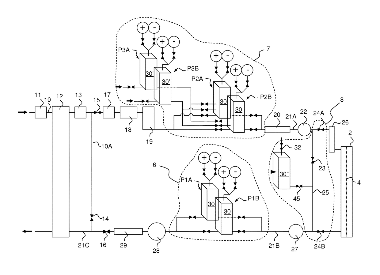
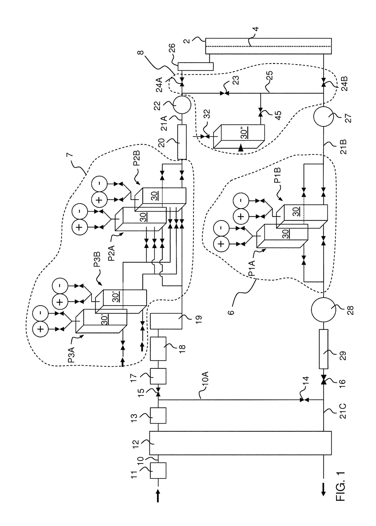
[0078]FIG. 1 is a fluid-flow diagram of a supply arrangement according to an embodiment of the invention. The supply arrangement is part of a dialysis machine and defines a flow path for a treatment solution (dialysis fluid) through a dialyzer 2. The dialyzer 2 is a conventional blood treatment device suitable for solute removal as well as ultrafiltration, such as a coil dialyzer, a parallel plate dialyzer, a hollow fiber dialyzer, etc. The dialyzer 2 generally has a blood side and a fluid side separated by a semipermeable membrane 4. In operation of the dialysis machine, an extracorporeal blood flow circuit (not shown) is connected to the blood side of the dialyzer 2 and arranged to circulate blood from a ...


PUM


Abstract

A cassette is provided for installation in a dialysis monitor to pump a treatment solution through a dialyzer. The cassette is a unitary component with a hydraulic manifold (53) and a pneumatic manifold (54) integrated into a body (52). The body (52) has connectors for connecting the hydraulic manifold (53) to the dialyzer and the pneumatic manifold (54) to a pneumatic pressure source. A set of solution pumps is integrated in the cassette, and each solution pump includes a pump cavity inside the body. The solution pumps are operable to displace the treatment solution through the hydraulic manifold (53) to and / or from the dialyzer by action of a reciprocating gas-liquid interface in the pump cavity (30) of the respective solution pump. The gas-liquid interface is formed directly between a gaseous substance and the treatment solution. A valve arrangement (58) is attached to the body (52) and operable to control admission of the gaseous substance and the treatment solution to the pump cavity (30) so as to reciprocate the gas-liquid interface and thereby pump the treatment solution through the hydraulic manifold (53). The cassette is configured to pump the treatment solution without moving parts inside the body (52).

Description

CROSS-REFERENCE TO RELATED APPLICATIONS[0001]The present application is a National Phase of International Application No. PCT / EP2013 / 075950, filed on Dec. 9, 2013, which claims priority to Sweden Patent Application No. 1251415-4, filed Dec. 13, 2012, and U.S. Provisional Application No. 61 / 736,669, filed Dec. 13, 2012, the entire contents of each of which is incorporated herein by reference and relied upon.TECHNICAL FIELD[0002]The present invention generally relates to the field of renal replacement therapy by the use of a dialysis system for extracorporeal blood processing, and in particular to a cassette for pumping a treatment solution through a dialyzer in such a dialysis system.BACKGROUND ART[0003]In extracorporeal blood processing, blood is taken out of a human or animal subject, processed in a dialyzer and then reintroduced into the subject by means of an extracorporeal blood flow circuit. Such extracorporeal blood processing includes hemodialysis, hemodiafiltration, hemofilt...

Claims


Application Information

Patent Timeline
Patent Type & Authority Patents(United States)
IPC IPC(8): A61M37/00A61M1/14A61M1/16F17D1/14
CPCA61M1/1601A61M1/14F17D1/14A61M1/165A61M2205/121A61M2205/128A61M2205/3334A61M2205/3375A61M2205/3389A61M2205/70A61M1/155A61M1/1565A61M1/156A61M1/1524A61M1/153
Inventor JANSSON, OLOFHOBRO, STUREJONSSON, LENNARTPERSSON, ANTON
Owner GAMBRO LUNDIA AB
Why Eureka
Try Eureka