Ultrasonic device unit, probe, electronic device and ultrasonic imaging device

a technology of ultrasonic imaging and ultrasonic devices, applied in mechanical vibration separation, medical science, diagnostics, etc., can solve the problems of increasing affecting the reliability of ultrasonic devices, so as to ensure the rigidity of the device substrate, prevent damage, and minimize the length of flexible printed boards

Active Publication Date: 2017-04-18
SEIKO EPSON CORP
View PDF11 Cites 2 Cited by
  • Summary
  • Abstract
  • Description
  • Claims
  • Application Information

AI Technical Summary

Benefits of technology

[0009]The ultrasonic device is received in the recess part. The ultrasonic device is disposed in the portion of the substrate that is recessed from the plane. The flexible printed board is superimposed on the ultrasonic device disposed in the recessed portion and connected to the same. Accordingly, compared to a case that the ultrasonic device is disposed at the planar part of the substrate, it is possible to suppress a bending of the flexible printed board. As the distance (length) of the flexible printed board decreases relative to its width, the flexible printed board is prevented from bending. And as the flexible printed board is kept from the bending, it is possible to shorten the length of the flexible printed board for connection of the flexible printed board. Accordingly, it is possible to securely miniaturize the ultrasonic device unit.
[0019](10) A ventilation path can be formed between the bottom surface of the recess part and the device substrate so as to be connected to the through-opening and communicate with the void space formed between the lateral surface of the recess part and the ultrasonic device. The interior spaces of the opening parts communicates with the exterior space of the substrate through the through-opening, the ventilation path and the void space. Ventilation is assured between the interior spaces of the opening parts and the exterior space of the substrate. Therefore, the interior spaces of the opening parts are not hermetically closed. The interior spaces of the opening parts easily follow the fluctuation in surrounding pressure. With this configuration, the thin film ultrasonic transducer elements can be securely prevented from being damaged. If the interior spaces of the opening parts are hermetically closed, the thin film ultrasonic transducer elements may be damaged due to the fluctuation in the surrounding pressure.

Problems solved by technology

But as the distance (length) of the flexible substrate is shortened relative to its width, it becomes more difficult to bend the flexible substrate.
If no sufficient distance is provided between the wall surface of the recess part and the ultrasonic device, it is difficult to make a connection using a flexible substrate.
Therefore, a predetermined distance is required between the wall surface of the recess part and the ultrasonic device, thereby making it difficult to miniaturize the ultrasonic device.
If the interior spaces of the opening parts are hermetically closed, the thin film ultrasonic transducer elements may be damaged due to the fluctuation in the surrounding pressure.

Method used


Image

  • Ultrasonic device unit, probe, electronic device and ultrasonic imaging device
  • Ultrasonic device unit, probe, electronic device and ultrasonic imaging device
  • Ultrasonic device unit, probe, electronic device and ultrasonic imaging device

Examples


first embodiment

[0042](2) Configuration of the Ultrasonic Device Unit

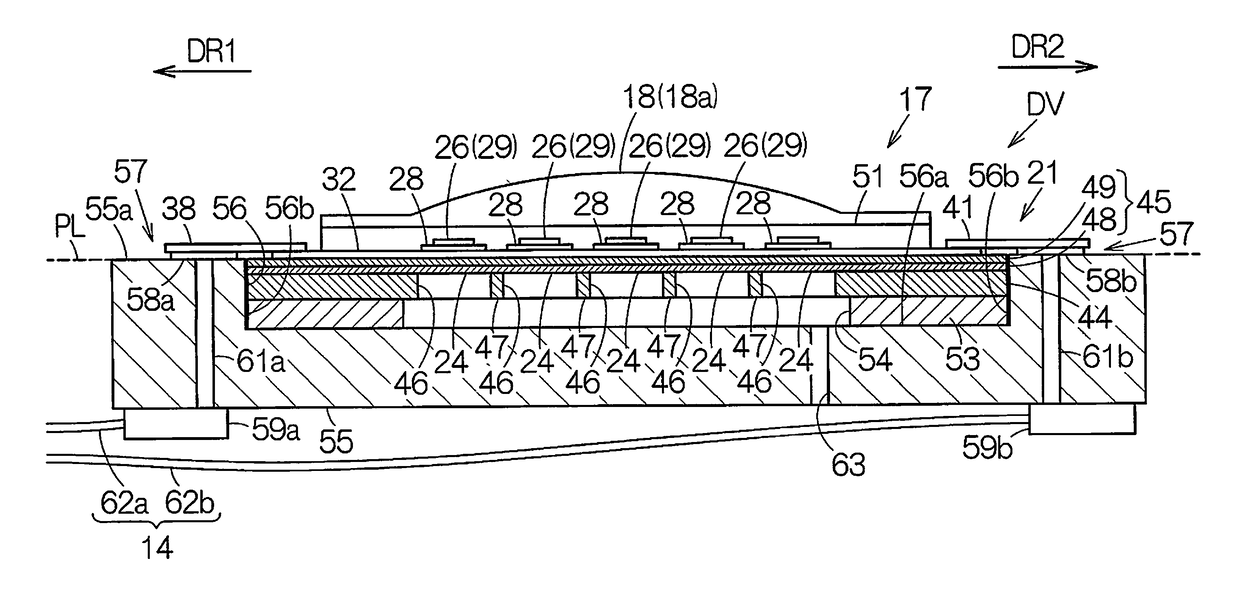
[0043]As shown in FIG. 3, the base 21 is provided with a substrate (device substrate) 44 and a cover film 45. The cover film 45 is formed over the entire surface of the substrate 44. The substrate 44 is provided with an opening part 46 for each element 23. The opening parts 46 are disposed in array form in the substrate 44. Each opening part 46 opens at a surface (second surface) on the rear side (opposite side) of the corresponding element 23. A contour of a region in which the opening parts 46 are disposed corresponds to a contour of the element array 22. A partitioning wall 47 is disposed between every two adjacent opening parts 46. The wall thickness of the partitioning wall 47 corresponds to an interval between the opening parts 46. The partitioning wall 47 defines two wall surfaces within planes which extend in parallel to each other. The wall thickness corresponds to a distance between the two wall surfaces. That is, the wa...

second embodiment

[0064](4) Configuration of Ultrasonic Device Unit

[0065]FIG. 6 schematically shows a configuration of an ultrasonic device unit DVa according to a second embodiment. In the ultrasonic device unit DVa, the reinforcing plate (plate member) 53a is formed as a continuous plate. That is to say, the through-opening 54 is not formed. The reinforcing plate 53a closes the opening parts 46 from the rear surface of the base 21. Herein, a plurality of linear grooves 68 are disposed in the surface of the reinforcing plate 53a. The grooves 68 partition the surface of the reinforcing plate 53a into a plurality of planes. Each groove 68 forms a single ventilation path commonly for the corresponding lines of the element array 22, for example. The ventilation path is connected to the opening parts 46 in one line. The cross-sectional shape of the groove 68 may be quadrangle, triangle, hemicycle or another.

[0066]In the reinforcing plate 53a, a longitudinal hole (ventilation path) 69 is formed for each g...

third embodiment

[0068](5) Configuration of Ultrasonic Device Unit

[0069]FIG. 7 schematically shows a configuration of an ultrasonic device unit DVb according to a third embodiment. In the ultrasonic device unit DVa, the reinforcing plate (plate member) 53a is formed as a continuous plate. That is to say, the through-opening 54 is not formed. The reinforcing plate 53a closes the opening parts 46 from the rear surface of the base 21. Herein, a plurality of linear grooves 68 are disposed in the surface of the reinforcing plate 53a. The grooves 68 partition the surface of the reinforcing plate 53a into a plurality of planes. The groove 68 forms a single ventilation path commonly for each row of the element array 22, for example. Each ventilation path is connected to the opening parts 46 in one row. The cross-sectional shape of the groove 68 may be quadrangular, triangular, hemicyclical or any other shape. Both ends of the groove 68 open at end surfaces of the reinforcing plate 53a facing the wall surfac...


PUM


Abstract

An ultrasonic device unit includes a substrate having a planar part and a recess part recessed from the planar part, an ultrasonic device which has an element array including a plurality of thin film ultrasonic transducer elements disposed in an array and is disposed in the recess part, a first flexible printed board, one end of which is superimposed on a portion of an array surface of the ultrasonic device and connected to the same, the other end of which is superimposed on a portion of the planar part and connected to the same, wherein the array surface of the ultrasonic device which the one end of the first flexible printed board is superimposed on is positioned within a plane including the planar part or a plane outside of the recess part.

Description

BACKGROUND[0001]1. Technical Field[0002]The present invention relates to an ultrasonic device unit, as well as a probe, an electronic device and an ultrasonic imaging device, which utilize the same.[0003]2. Related Art[0004]An ultrasonic device unit having an ultrasonic device with bulk type piezoelectric elements being disposed in an array is generally known. For example, in an ultrasonic device unit described in JP-A-2008-79909, a recess part is formed to be recessed from a plane, and the ultrasonic device is disposed in the recess part. The ultrasonic device has bulk type piezoelectric elements which are vertically interposed between a common electrode and a signal electrode. The common electrode is connected to a land on the plane by means of wire bonding, wherein a flexible substrate is connected to the signal electrode at a lower position than the plane.[0005]JP-A-2008-79909 is an example of related art.[0006]In the configuration described in JP-A-2008-79909, the flexible subs...

Claims


Application Information

Patent Timeline
Patent Type & Authority Patents(United States)
IPC IPC(8): B06B1/06A61B8/00
CPCB06B1/0622A61B8/4427A61B8/4483
Inventor YOSHIDA, KAZUKIKANO, KAZUYUKINAKAZAWA, YUSUKE
Owner SEIKO EPSON CORP
Why Eureka
Try Eureka