High efficiency fluid separation device

a technology of fluid separation and high efficiency, which is applied in the direction of liquid degasification, separation process, chemistry apparatus and processes, etc., can solve the problems of mixing detrimental to the process, the performance of bigger tanks is worse, and the labs were startling and very disappointing, so as to maximize the utilization of the tank, maximize the retention time, and promote the separation of smaller water droplets

Active Publication Date: 2017-04-25
KBK IND
View PDF11 Cites 7 Cited by
  • Summary
  • Abstract
  • Description
  • Claims
  • Application Information

AI Technical Summary

Benefits of technology

[0031]The oil rises at the minimum velocity, maximizing retention time. The lower rise rate of the oil promotes the separation of smaller water droplets. Larger and heavier water droplets can now counter-flow downward and into the water layer below, completing the dehydration process to a degree not heretofore thought possible in atmospheric gun barrel tank systems.
[0032]As the oil nears the top of the oil layer, it is collected uniformly throughout the entire circumference of the tank employing a circular oil collection trough, thus maximizing the utilization of the tank and completing the dehydration process. The entire top edge of the circular oil collection trough is in the form of a plurality of V-shaped notches that insure uniform collection of oil into the oil collection trough from around the entire circumference of the gun barrel tank.

Problems solved by technology

Even then, i.e. approximately 150 years ago, it was obvious that mixing is detrimental to the process of separating water and oil.
The results from these labs were startling and very disappointing.
Bigger tanks had been thought to be better for separating oil from water, but in most cases, test showed that bigger tanks actually performed worse.
One problem with previous gun barrel designs is that it had always been presumed that fluids naturally distributed uniformly and flowed through the entire gun barrel tank uniformly.
When compared with the original supposition that oil retention times were hours long, these tests were quite eye opening, and contrary to the assumptions made about gun barrel performance for over 100 years.
At that point, skepticism about the wisdom of the past began to set in.
Every conceivable idea was tried, and surprisingly, most failed.
Too little effort had been given to the selection of oil process equipment in the past by oil companies, resulting in millions of dollars of unnecessary costs.
Many oil operators simply pick up the phone and order a separator, a gun barrel or heater treater, a couple of oil tanks, a water tank, or whatever they ordered last time, even though the equipment they are ordering is not efficient at separating oil, gas, and solids from the produced oil.
However, the new technologies we currently have available are completely different than the technologies available when our predecessors got away with a more casual approach to selecting new process equipment.
It also shouldn't be too surprising that yesterday's process equipment designed for low water cut conditions doesn't fit well in today's higher water cut operations.
Thus, use of older type separation equipment costs the oil industry a fortune each year.

Method used


Image

  • High efficiency fluid separation device
  • High efficiency fluid separation device
  • High efficiency fluid separation device

Examples


Embodiment Construction

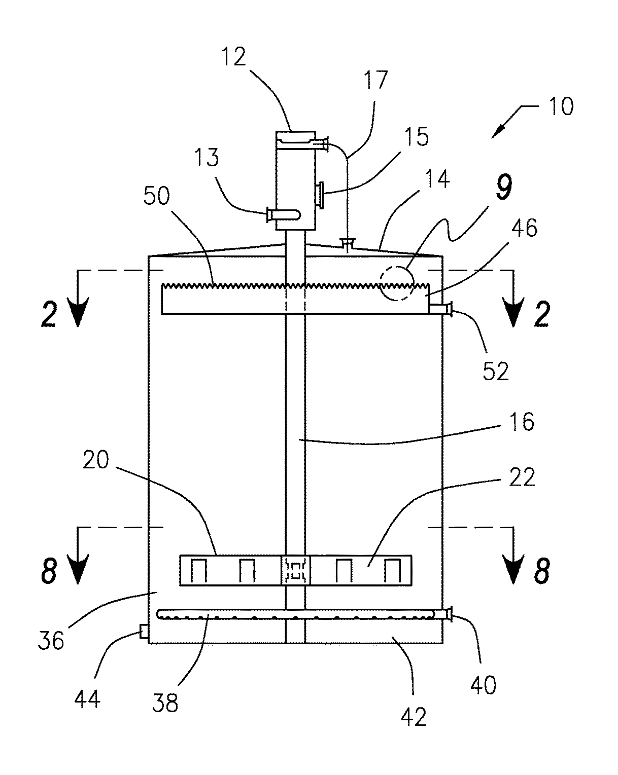
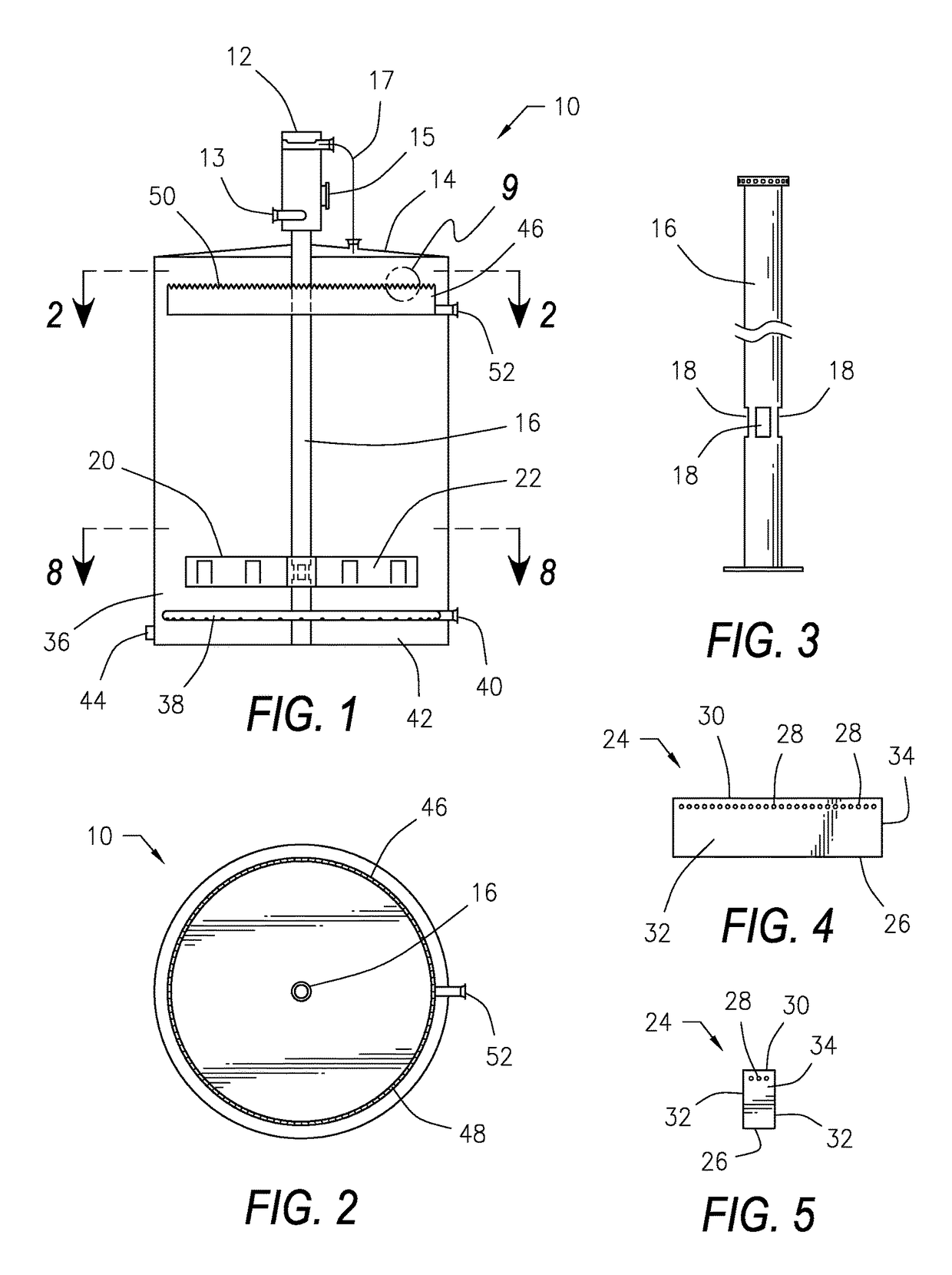
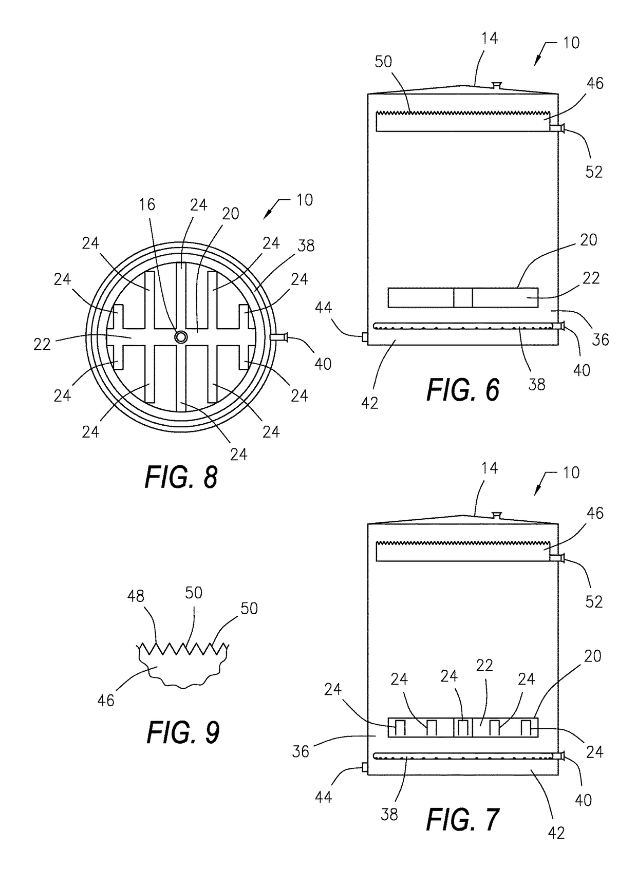
[0042]Referring now to the drawings, and initially to FIG. 1, there is illustrated a high efficiency gun barrel tank 10 that is constructed in accordance with a preferred embodiment of the present invention. The tank 10 employs a unique dual phase hydraulics approach to achieve uniform distribution of the crude oil mixture within the tank 10 and uniform collection of the resulting separated crude oil from the tank 10. As in all gun barrels or wash tanks, the inlet fluid in the present tank 10 is first degassed in a degassing boot 12. The crude oil mixture enters the degassing boot 12 via a fluid inlet 13. The degassing boot 12 is located on top 14 of the tank 10 and removes the free gas from the liquids. The free gas exits the degassing boot 12 via a gas outlet 15 provided on the degassing boot 12. The degassing boot 12 communicates with gas located within the top 14 of the tank 10 via a gas equalizing line 17 to equalize pressure between the tank 10 and the degassing boot 12.

[0043]...


PUM

PropertyMeasurementUnit
oil retention timeaaaaaaaaaa
areaaaaaaaaaaa

Abstract

A gun barrel tank for treating raw crude oil mixtures. The fluid mixture enters through a degassing boot where gas is separated from the liquid. The liquid travels through a central column to a horizontal hydraulic distributor located in the lower area of the tank, first entering a central distributor trough, then passing into open bottom horizontal inverted lateral troughs and finally out through a plurality of metering orifices provided near the top edges of the lateral troughs to provide uniform distribution of the liquid in the tank. A circular oil collection trough provided at the top of the tank has a plurality of V-shaped notches on its top edge over which oil flows into an oil collection trough to provided uniform collection of the separated crude. A circular water collector in the bottom of the tank removes separated water, and solids are removed from the bottom of the tank.

Description

BACKGROUND OF THE INVENTION[0001]1. Field of the Invention[0002]The present invention is an improved cylindrical tank that is known in the petroleum industry as a gun barrel. The present gun barrel is used to separate small amounts of water from large amounts of crude oil. The improvements in the gun barrel include features that create more uniform distribution of inlet fluid within the tank and more uniform collection of outlet fluid in the form of oil from the tank.[0003]2. Description of the Related Art[0004]Oil-water separation became a necessity in Drake's first well in Titusville, Pa. As that well began to water out, a system to separate the water was needed. The so-called “gun barrel” tank was developed to meet that need.[0005]Gun barrel designs took a couple of generations to mature. But when they finally did, they became a standard of the industry that has survived ever since. The gun barrel tank, which is also called a “wash tank” in some circles, became universally applie...

Claims


Application Information

Patent Timeline
Patent Type & Authority Patents(United States)
IPC IPC(8): B01D19/00B01D17/02
CPCB01D17/0211B01D17/0214B01D19/00
Inventor BALL, WILL D.
Owner KBK IND
Why Eureka
Try Eureka