Cutter hub pin drive mechanism and quick disconnect hub for an underfluid pelletizer

a technology of hub pin drive mechanism and hub, which is applied in the field of pelletizers, can solve the problems of affecting pelletizer performance, less surface contact between the keys and their corresponding slots, and higher stress on the torque-bearing keys, so as to reduce irregular wear patterns that impede the forward adjustment movement of the cutting blade, and reduce wear

Active Publication Date: 2017-04-25
GALA INDUSTRIES INC
View PDF11 Cites 3 Cited by
  • Summary
  • Abstract
  • Description
  • Claims
  • Application Information

AI Technical Summary

Benefits of technology

[0017]The present invention also includes a quick disconnect hub for a pelletizer or a cutter hub pin drive mechanism. The quick disconnect hub is configured to secure the pelletizer shaft to the cutter hub holder with a retaining element. To separate the cutting assembly from the pelletizer with minimal effort in order to clear the cutting chamber from agglomerated polymer and the like, the quick disconnect hub is separated from the retaining element, allowing the pelletizer shaft to be pulled out of the cutter hub holder while the cutter hub remains in the cutting chamber. Once the chamber is cleared, the pelletizer shaft can be easily reconnected to the cutter hub holder by resecuring the quick disconnect hub with the original or a replacement retaining element.
[0029]It is still another object of the invention to provide a pelletizer with quick disconnect hub in accordance with the preceding two objects in which the disconnect device is not complex in structure and can be manufactured at low cost but yet efficiently enables the pelletizer to be disconnected from the cutting chamber easily and quickly without the need for complicated or lengthy disassembly procedures.

Problems solved by technology

Several problems with this design may arise.
Further, due to the nature of welding, the keys may not be precisely positioned to exactly match the key slots in the pelletizer shaft, resulting in less than the desired amount of surface contact between each of the keys and their corresponding slot.
As a result, torque that is transmitted from the cutter hub to the pelletizer shaft during operation of the pelletizer may be borne by less than all of the keys, creating even higher stresses on the torque-bearing keys which can impair pelletizer performance and / or lead to breakage of the keys.
Second, the keys can wear into the sides of the key slots in the pelletizer shaft 100.
The wear pattern of these notches creates a “hook” that can trap the keys and prevent the spring 125 from pushing the cutter hub holder 115 forward to compensate for blade wear, causing poor cutting performance and thus poor pellet quality.
Fines packed in the key slots can also produce cross contamination from one pelletizing run to the next.
These keys can also wear into the sides of the key slots in the pelletizer shaft 200 since they do not extend out of the end of the pelletizer shaft 200, again creating the “hook” wear pattern that requires more effort to push the cutter hub holder 215 forward to compensate for blade 225 wear and causing poor cutting performance and thus poor pellet quality.
An additional problem with both the FIG. 1 and FIG. 2 designs is that the cutting area within the cutting chamber or water box can become agglomerated with molten polymer or polymer blend material, allowing the polymer to wrap around the cutter hub and blades and flow either up the slurry outlet piping 150, 245 or down the water or fluid inlet piping 145, 240, or into both the inlet and the outlet.
Unfortunately, rather than undertaking disassembly procedures such as those just described, many operators will try to introduce pry bars to increase leverage to get the pelletizer separated from the cutting chamber.
The heavy duty pry bars can damage the precision mating surfaces of the pelletizer front-end and the connecting flange of the cutting chamber.
Further, the pry bars put very high stresses on the various components on the front end and throughout the pelletizer and its motor.
Needless to say, such forceful separation can severely damage the pelletizer and its components, creating costly failures, extensive down time awaiting replacement parts to repair the damage, and / or safety hazards.

Method used


Image

  • Cutter hub pin drive mechanism and quick disconnect hub for an underfluid pelletizer
  • Cutter hub pin drive mechanism and quick disconnect hub for an underfluid pelletizer
  • Cutter hub pin drive mechanism and quick disconnect hub for an underfluid pelletizer

Examples


first embodiment

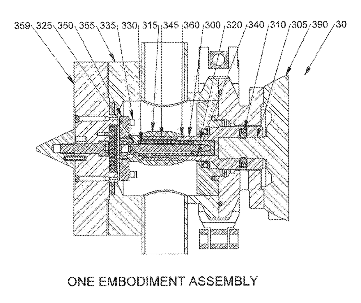
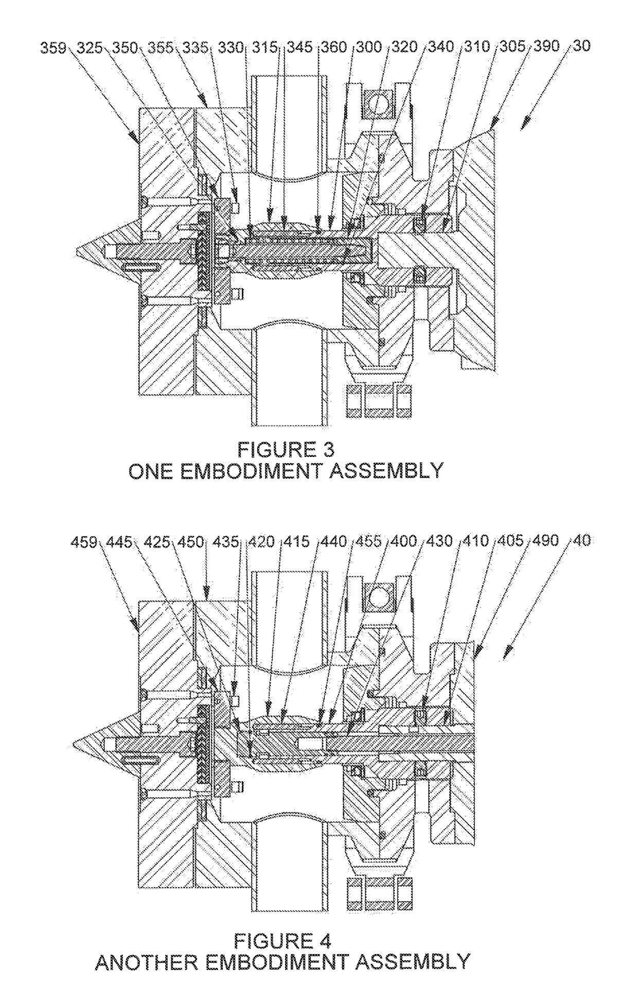
[0053]the present invention is shown in FIGS. 3, 7, 7A and 9. The pelletizer, generally designated by reference numeral 30, includes a pelletizer shaft 300 coupled to a motor shaft 305, a cutter hub 350 with cutter blades 335, a cutter hub holder 315, a cutting chamber 355, a die plate 359, a cutter hub pin drive mechanism including a plurality of drive pins 345, a sealing member 360, a disconnect hub 320 and a retainer ring 340. The pelletizer shaft 300 is bolted to the motor shaft 305 of motor 390 with set screws 310. The cutter hub holder 315 is secured to the disconnect hub 320 with a bolt 325. A spring 330 is provided for adjustment of the cutter hub holder 315 and blade position as the blades 335 wear.

[0054]The cutter hub pin drive mechanism includes multiple drive pins 345, with typically 6 to 12 being used depending upon various factors including but not limited to the model of the pelletizer, the power of the motor, space constraints and the diameter of the pelletizer shaft...

second embodiment

[0062]the present invention is shown in FIGS. 4, 8, 8A and 10. The pelletizer, generally designated by reference numeral 40, includes a pelletizer shaft 400 coupled to a motor shaft 405, a cutter hub 445 with cutter blades 435, a cutter hub holder 415, a cutting chamber 450, a die plate 459, a cutter hub pin drive mechanism including a plurality of drive pins 440, a sealing member 455, a quick disconnect hub 425 and a retainer ring 420. The pelletizer shaft 400 is bolted to the motor shaft 405 of motor 490 with set screws 410. The pelletizer shaft has a motion rod 430 that is threadedly coupled to the quick disconnect hub 425, with the connection between the hub 425 and the motion rod 430 then being used to secure the pelletizer shaft to the cutter hub holder 415 and cutter hub assembly.

[0063]As in the first embodiment, the cutter hub pin drive mechanism includes multiple drive pins 440, with typically 6 to 12 being used depending upon various factors including but not limited to th...

third embodiment

[0069]the present invention is shown in FIGS. 11, 12, 12A and 13. The pelletizer, generally designated by reference numeral 50, includes a pelletizer shaft 500 with a motion rod 520 coupled to a motor shaft 505, a cutter hub 540 with cutter blades 530, a cutter hub holder 515, a cutting chamber 545, a die plate 559, a cutter hub pin drive mechanism including a plurality of drive pins 535, and a sealing member 550. The pelletizer shaft 500 is bolted to the motor shaft 505 of motor 590 with set screws 510. The cutter hub holder 515 is retained on the pelletizer shaft 500 through threaded engagement with the motion rod 520. The motion rod 520 is used to adjust and fix the position of the cutter hub 540 relative to the die plate 559 as the blades 530 wear down. Once the motion rod is positioned as desired, the set screw 525 is used to secure the motion rod to the cutter hub holder.

[0070]Like the first and second embodiments, the cutter hub pin drive mechanism includes multiple drive pin...


PUM

PropertyMeasurementUnit
torqueaaaaaaaaaa
areaaaaaaaaaaa
diameteraaaaaaaaaa

Abstract

A cutter hub pin drive mechanism and a quick disconnect hub for a pelletizer and a pelletizer having a cutter hub pin drive mechanism are provided. The pelletizer has a cutter hub that includes a cutter hub holder which is engaged with the pelletizer shaft through a plurality of drive pins. The drive pins ride in drive pin channels formed by grooves cut into an inner surface of the cutter hub holder and aligned grooves formed in the outer surface of the forward end of the pelletizer shaft. By machining of grooves into the cutter hub holder and shaft to form channels that receive the drive pins, more precise engagement between the pelletizer shaft, cutter hub holder and drive pins is obtained, resulting in improved torque transmission from the shaft to the cutter hub. Also provided is a seal around the pelletizer shaft to prevent the egress of fines into the drive pin area which might otherwise interfere with the unobstructed movement of the cutter hub holder necessary to adjust blade position. Finally, a quick disconnect hub is provided by which the pelletizer shaft can be readily disconnected from the cutting assembly to facilitate the removal of agglomerated polymer in the cutting chamber.

Description

[0001]This application is based upon provisional application, U.S. Ser. No. 61 / 788,648, filed Mar. 15, 2013, and hereby claims the priority thereof to which this application is entitled.BACKGROUND OF THE INVENTION[0002]Field of the Invention[0003]The present invention is related to the field of pelletizers for production of pellets from polymer containing materials and other pelletizable formulations.[0004]Description of the Related Art[0005]Various pelletizer designs are disclosed in U.S. Pat. No. 5,059,103 (“the '103 patent”), U.S. Pat. No. 7,033,152 (“the '152 patent”), and U.S. Pat. No. 8,303,871 (“the '871 patent”), all of which patents are co-owned by the applicant and assignee of the instant application. The disclosures of the '103 patent, the '152 patent and the '871 patent are relevant to the subject matter of the instant application and therefore these three patents are hereby expressly incorporated herein by reference as if fully set forth in the instant application.[0006...

Claims


Application Information

Patent Timeline
Patent Type & Authority Patents(United States)
IPC IPC(8): B29B9/06B26D5/02
CPCB29B9/065B26D5/02B29K2105/0067
Inventor SELL, JOHN A.
Owner GALA INDUSTRIES INC
Why Eureka
Try Eureka