
Work vehicle with controls for regenerating exhaust gas purification device

Active Publication Date: 2017-04-25
YANMAR POWER TECHNOLOGY CO LTD
View PDF5 Cites 1 Cited by
  • Summary
  • Abstract
  • Description
  • Claims
  • Application Information

AI Technical Summary

Benefits of technology

The patent text describes a work vehicle that includes an engine with an exhaust gas purification device. The invention is designed to prevent a reduction in temperature of the exhaust gas purification device, which can cause particulate matter to accumulate and reduce its purification capacity. The invention includes a display device that informs the operator of the vehicle about the purification device and allows for regeneration control to remove particulate matter. The display device notifies the operator when the purification device reaches a predetermined level of particle accumulation and urges them to activate the regeneration control. The invention includes a controller that controls the engine and the display device, and only executes the regeneration control when the operator activates the regeneration switch. This alleviates the load on the engine controller and lowers the cost of the regeneration switch. In summary, the technical effect of the invention is to improve the purification capacity of the exhaust gas purification device and execute regeneration control in a more efficient and cost-effective manner.

Problems solved by technology

However, when the regeneration control is automatically executed, the engine is automatically driven in a high-load state, and when work is conducted under low load, not only the engine behaves against an operator's will, but also driving troubles occur in the engine or a work machine.
Also, in some cases, a travelling machine body or the work machine of the work vehicle needs to be stopped due to the regeneration control, and there is a case where the operator cannot determine operations that are actually required, through the mere request of the execution of the regeneration control.

Method used


Image

  • Work vehicle with controls for regenerating exhaust gas purification device
  • Work vehicle with controls for regenerating exhaust gas purification device
  • Work vehicle with controls for regenerating exhaust gas purification device

Examples


Embodiment Construction

[0031]Hereinafter, an embodiment, in which the present invention is embodied, will be described based on drawings and exemplified by a tractor as an agricultural work vehicle.

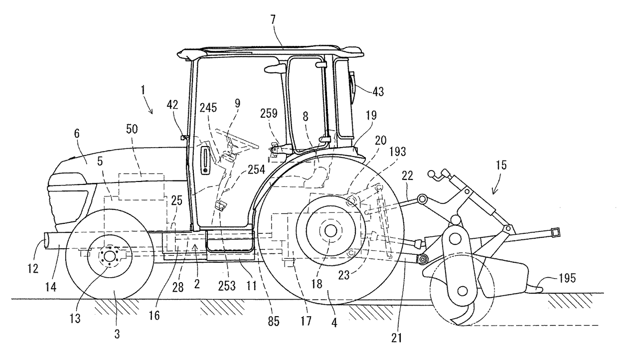
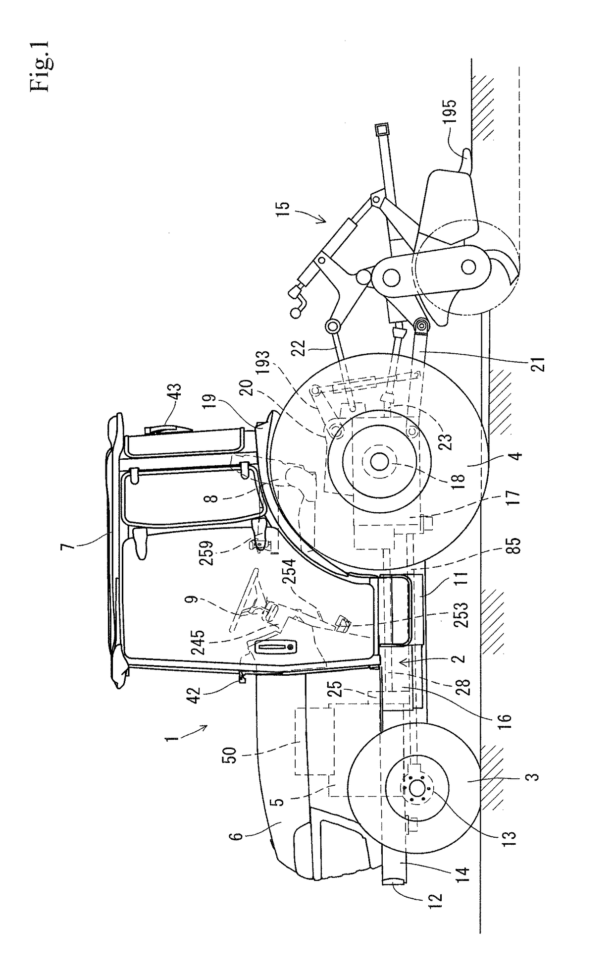
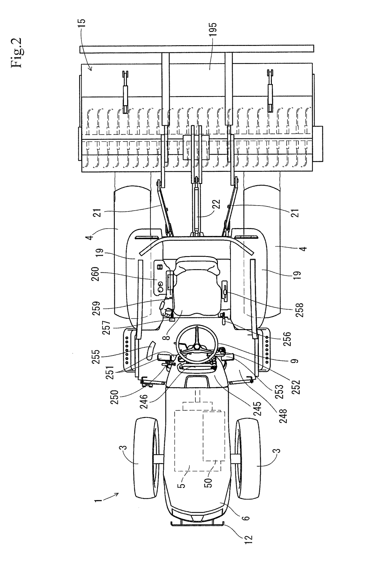
[0032]To begin with, the outline of the tractor will be described referring to FIGS. 1 and 2. A travelling machine body 2 of a tractor 1 of the present embodiment is supported by a pair of right and left front wheels 3 as a travelling unit and a pair of right and left rear wheels 4 in a similar manner. It is constituted such that the rear wheels 4 and the front wheels 3 are driven by a common-rail diesel engine 5 (hereinafter merely referred to as an engine) as a power source mounted on the front portion of the travelling machine body 2, which allows the tractor 1 to move forward and backward in running. The engine 5 is covered with a hood 6. A cabin 7 is arranged on the upper surface of the travelling machine body 2, and a maneuvering seat 8 and a steering handle (round handle) 9 that moves the steering direct...


PUM


Abstract

Regarding a work vehicle that includes an engine mounted on a travelling machine body and an exhaust gas purification device arranged in an exhaust gas path of the engine, it is an object to prevent the regeneration control of the exhaust gas purification device from being executed against operators' will. The work vehicle of the present invention includes a regeneration switch 329 for executing the regeneration control of an exhaust gas purification device 50, a meter panel 246 for displaying the situation of driving operations of a travelling machine body 2, and a work device 15. Then, when it is assumed that a predetermined amount or more of particulate matter in the exhaust gas purification device 50 is accumulated, the meter panel 246 notifies a regeneration control request warning and displays characters that urge stoppages of work of the work device 15 and travelling of the travelling machine body 2.

Description

TECHNICAL FIELD[0001]The present invention of the instant application relates to a work vehicle, such as an agricultural work vehicle, in which an exhaust gas purification device is mounted on the side of an upper portion of an engine.BACKGROUND OF THE INVENTION[0002]These days, with the application of high-level emission control regarding diesel engines (hereinafter merely referred to an engine), it has been demanded that an exhaust gas purification device for purifying and treating air pollution substances in exhaust gas is mounted in agricultural work vehicles or construction work machines in which an engine is mounted. As the exhaust gas purification device, a diesel particulate filter (the exhaust gas purification device) for collecting particulate matter and the like in the exhaust gas has been known (for example, see Patent Literature 1).PATENT LITERATURE[0003]PTL1: Japanese Unexamined Patent Application Publication No. 2008-31955SUMMARY OF THE INVENTION[0004]As the work vehi...

Claims


Application Information

Patent Timeline
IPC IPC(8): B62D49/00F01N3/023F02D41/02F01N9/00F01N3/035F02D41/40F02D41/22
CPCF01N3/023B62D49/00F01N9/002F02D41/029F01N3/035F01N2590/08F02D41/405F02D2041/228F02D2200/604F01N3/0235
Inventor KOIKE, YUUSUKEIWATA, AKIMICHIYOKOYAMA, KAZUHISA
Owner YANMAR POWER TECHNOLOGY CO LTD
Learn More