Methods and systems for low-pressure exhaust gas recirculation

a low-pressure exhaust gas and recirculation technology, applied in the direction of pump control, non-positive displacement fluid engine, pump control, etc., can solve the problems of premature failure of the air filter, reduce the amount of egr containing, and reduce the amount of air flow

Active Publication Date: 2017-04-25
FORD GLOBAL TECH LLC
View PDF14 Cites 2 Cited by
  • Summary
  • Abstract
  • Description
  • Claims
  • Application Information

AI Technical Summary

Benefits of technology

[0003]The EGR system may be equipped with a compressor recirculation valve (CRV) contained within a CRV passage. When opened, the CRV may serve to reduce compressor surge during certain conditions by recirculating the intake mixture downstream of the compressor back to the intake passage upstream of the compressor.
[0005]The inventors herein have recognized the above issues and have devised numerous approaches to at least partially address them. In one example, a method for controlling air flow through a compressor recirculation passage, comprising: during a first condition: reducing air flow through the compressor recirculation passage based on a margin, the margin based on a rate of air flow at a compressor inlet, a rate of air flow through the compressor recirculation passage, and a rate of EGR flow. In this way, the CRV recirculation flow may be controlled to be less than the amount that could potentially backflow into an air filter disposed in the air intake passage, thus preventing EGR contained in the CRV recirculation flow from fouling the air filter with soot, oil and water.
[0006]In another example, a system for an engine, comprising: a turbocharger comprising a compressor arranged in an intake passage and a turbine arranged in an exhaust passage; a low-pressure exhaust gas recirculation (EGR) system including an EGR passage coupling the exhaust passage with the intake passage upstream of the compressor; a compressor recirculation passage coupling the intake passage downstream of the compressor with the intake passage upstream of the compressor; a controller holding instructions to reduce air flow through the compressor recirculation passage based on a margin, the margin based on a rate of air flow at a compressor inlet, subtracting a rate of air flow through the compressor recirculation passage, and further subtracting a rate of EGR flow through the EGR passage. In this way, the system will reduce the amount of EGR containing CRV recirculation flow that may enter the air intake passage, despite engine compartmental restrictions that limit the volume of the air intake. Reducing this amount may allow for use of the EGR system while limiting the concentration of contaminants that may foul an air filter disposed in the air intake passage.
[0007]In yet another example, a method for an engine, comprising: during a first condition where a compressor recirculation valvecompressor recirculation valve is open: measuring a rate of an air flow at a compressor inlet; measuring a rate of an air flow through a compressor recirculation passage; measuring a rate of an EGR flow through a low-pressure EGR passage; determining a value for a margin based on current values for the rate of air flow at the compressor inlet, the rate of air flow through the compressor recirculation passage, and the rate of EGR flow through the low-pressure EGR passage; closing the compressor recirculation valvecompressor recirculation valve when the value for the margin is less than a threshold. In this way, air pressure and air / gas flow rates in the air intake and EGR systems of an engine may be continuously monitored and adjusted based on engine operating conditions so as to prevent large volume backflow events that may result in EGR containing gas fouling components disposed in the air intake system, such as an air filter.

Problems solved by technology

High volumes of backflow through the CRV passage may allow the EGR containing air to reach the intake air filter, fouling and causing premature failure of the air filter, particularly for systems with a small volume between the air filter and the compressor.
This is of particular concern as engines equipped with LP-EGR systems may operate close to compressor surge conditions, requiring high volumes of backflow during conditions of acceleration or high load immediately followed by sudden deceleration.

Method used


Image

  • Methods and systems for low-pressure exhaust gas recirculation
  • Methods and systems for low-pressure exhaust gas recirculation
  • Methods and systems for low-pressure exhaust gas recirculation

Examples


Embodiment Construction

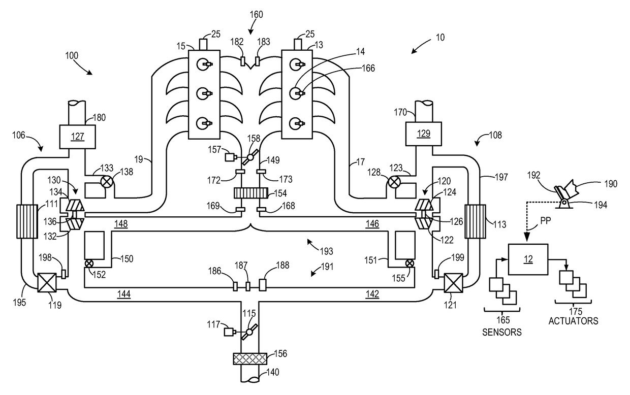
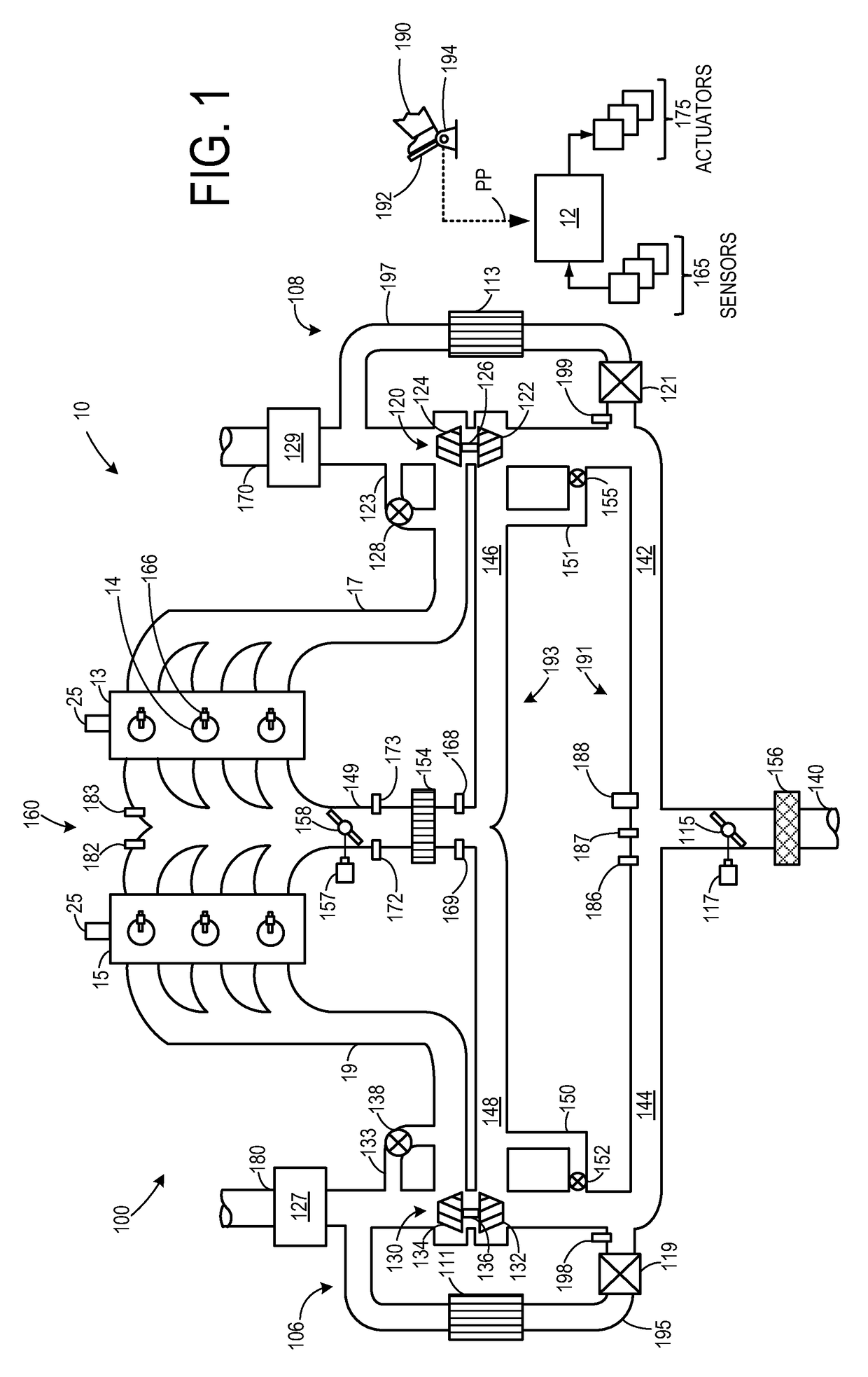
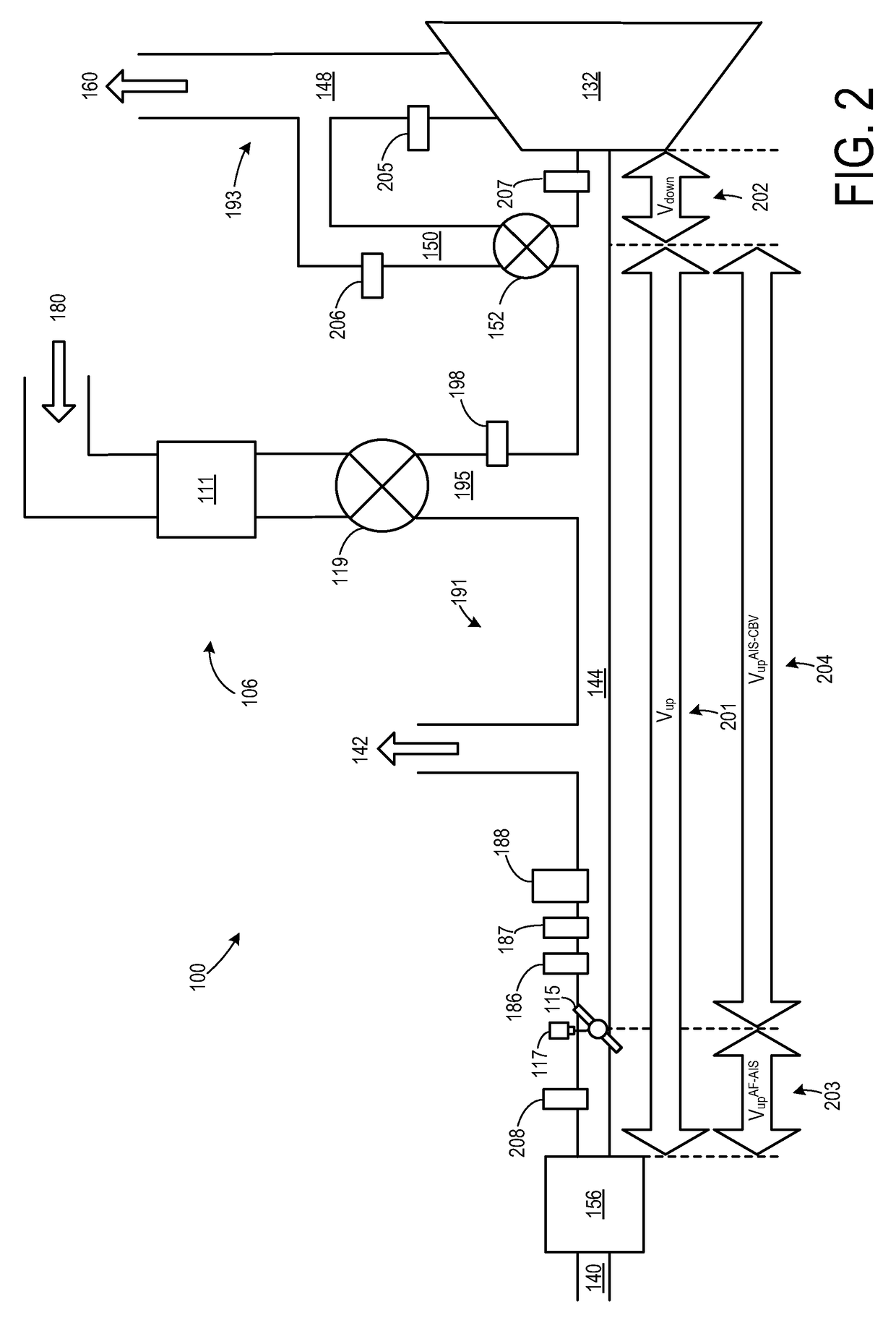
[0014]The following description relates to controlling flow through a compressor recirculation valve passage during the operation of a turbocharged internal combustion engine. As shown in the example embodiment of FIG. 1, an engine system may include two branches, each equipped with a turbocharger and EGR system. As shown in more detail in FIG. 2, each branch may be broken into various segments and sections, with sensors placed in each section for measuring local air and gas flow rates and / or local air and gas pressures. By monitoring local air and gas flow rates and pressures, it may be possible to mitigate fouling of an air filter within the engine by controlling the flow through a compressor recirculation valve passage, as shown by an example method in FIG. 3. FIG. 4 depicts an example timing plot using the method shown in FIG. 3 to control the turbocharged engine of FIGS. 1 and 2.

[0015]FIG. 1 shows a schematic depiction of an example turbocharged engine system 100 including a mu...


PUM


Abstract

A method for controlling air flow through a compressor recirculation passage, comprising: during a first condition: reducing air flow through the compressor recirculation passage based on a margin, the margin based on a rate of air flow at a compressor inlet, a rate of air flow through the compressor recirculation passage, and a rate of EGR flow. In this way, the CRV recirculation flow may be controlled to be less than the amount that could potentially backflow into an air filter disposed in the air intake passage, thus preventing EGR contained in the CRV recirculation flow from fouling the air filter with soot, oil and water.

Description

CROSS REFERENCE TO RELATED APPLICATION[0001]This application claims priority to U.S. Provisional Patent Application No. 61 / 876,595, entitled “METHODS AND SYSTEMS FOR LOW-PRESSURE EXHAUST GAS RECIRCULATION,” filed Sep. 11, 2013, the entire contents of which are hereby incorporated herein by reference for all purposes.BACKGROUND AND SUMMARY[0002]Internal combustion engines may utilize recirculation of exhaust gas from an engine exhaust system to an engine intake system, a process referred to as exhaust gas recirculation (EGR), to reduce regulated emissions. In a turbocharged engine including a turbine and a compressor, exhaust may be recirculated through a high-pressure (HP) EGR system and / or a low-pressure (LP) EGR system. In an HP EGR system, exhaust is drawn from upstream of the turbine and is mixed with intake air downstream of the compressor. In an LP EGR system, exhaust is drawn from downstream of the turbine and mixed with intake air upstream of the compressor.[0003]The EGR sys...

Claims


Application Information

Patent Timeline
Patent Type & Authority Patents(United States)
IPC IPC(8): F04D27/02F04D25/02F02C6/12
CPCF04D27/0207F02C6/12F04D25/024F04D27/0223
Inventor BIDNER, DAVID KARLBUCKLAND, JULIA HELEN
Owner FORD GLOBAL TECH LLC
Why Eureka
Try Eureka